


Page 5
ELECTRICAL REQUIREMENTS
WARNING - If the power cord is ever damaged, it must be replaced by the manufacturer or its service agent with
a special cord available from the manufacturer or its service agent in order to avoid a hazard.
Refer to Data Plate on the Brewer, and local/national electrical codes to determine circuit requirements.
ELECTRICAL HOOK-UP
CAUTION – Improper electrical installation will damage electronic components. Damage caused by incorrect
electrical connections is not covered by warranty.
1. An electrician must provide electrical service as specified in conformance with all local, state and federal
electrical codes.
2. Using a voltmeter, check the voltage and color coding of each conductor at the electrical source.
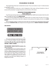
NOTE - The brewer is shipped without a plug on the power cord. Qualified service personnel must select
and install the proper UL listed grounding type attachment plug specified on the rear of the brewer.
3. Install the specified plug on the attached power cord.
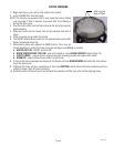
4. Remove the front access panel to gain access to the terminal block.
5. Connect the brewer to the power source and verify the voltage at the terminal block before proceeding.
6. If plumbing is to be hooked up later be sure the brewer is disconnected from the power source. If plumbing
has been hooked up, the brewer is ready for Initial Set-Up.
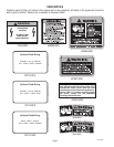
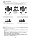
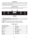
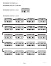
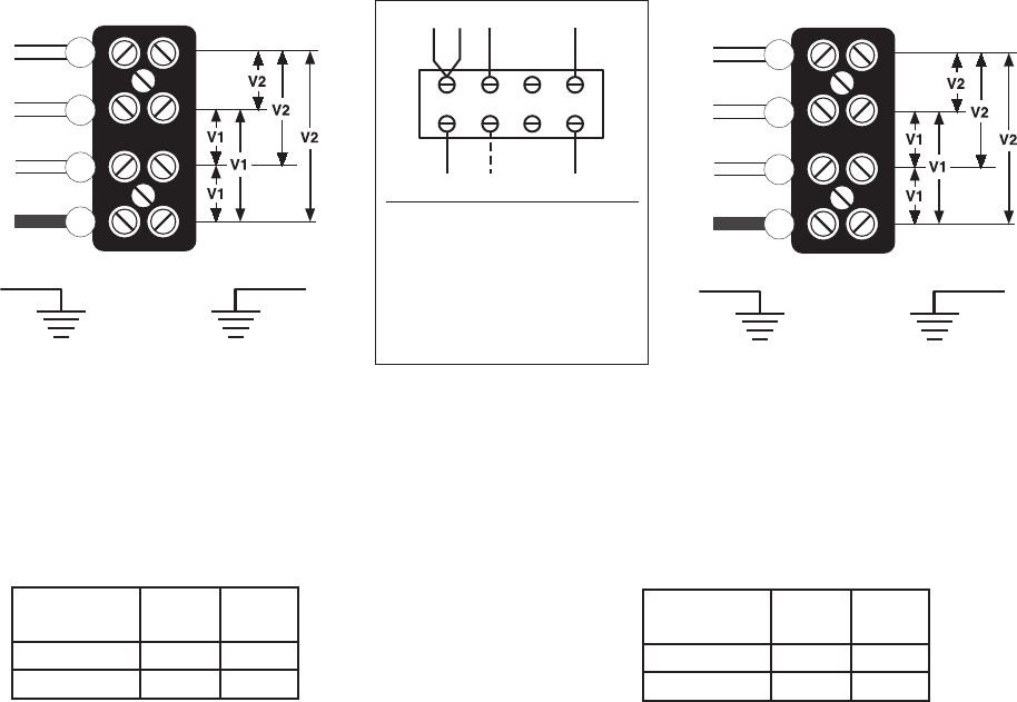
L1, L2, L3, are the 3 phases
V1 = Phase to phase voltage, between any 2 phases.
V2 = Phase to neutral voltage, L1 to neutral must be 120V.
SYSTEM
VOLTAGE V1 V2
208 208 120
240 240 120
120/208 and 120/240 volt ac
three phase, 50/60 Hz models
Note: This electrical service consists of 4 cur-
rent carrying conductors (Neutral, L1, L2 and
L3) and a separate conductor for earth ground.
40119 030608
GREEN GREEN
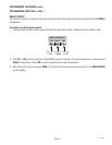
400/230V volt ac three phase,
50/60 Hz models
Note: This electrical service consists of 4 cur-
rent carrying conductors (Neutral, L1, L2 and
L3) and a separate conductor for earth ground.
BLK
RED
BLU
WHI
L1
L2
L3
N
L1, L2, L3, are the 3 phases
V1 = Phase to phase voltage, between any 2 phases.
V2 = Phase to neutral voltage, L1 to neutral must be 230V.
SYSTEM
VOLTAGE V1 V2
400 400 230
230 230
GREEN GREEN
BLK
RED
BLU
WHI
L1
L2
L3
N
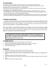
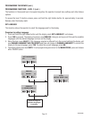
L1 L2 L3 N
BLK
BLU
RED
WHI
TO MACHINE
FROM POWER SOURCE
FOR SINGLE PHASE OPERATION
MOVE BLU WIRE INTO TERMINAL
BLOCK WITH BLACK WIRE.
CONNECT INPUT WIRING TO:
L1, L2 & N FOR 120/208V &
120/240V MODELS,
L1 & N for 230V MODELS.