


19
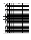
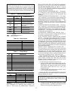
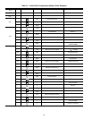
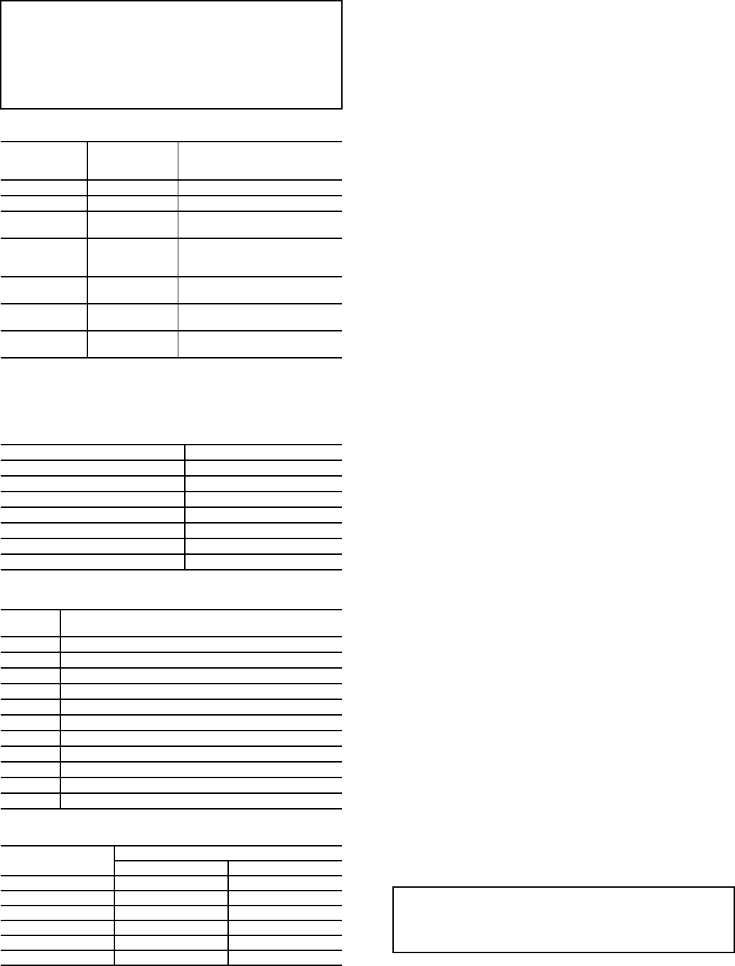
Table 15 — Thermistor Designations
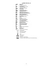
LEGEND
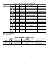
Table 16 — Status Inputs
Table 17 — Output Relays
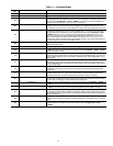
Table 18 — CCN Communication Bus Wiring
Sensors — The electronic control uses 2 to 7 thermistors to
sense temperatures for controlling chiller operation. See
Table 15. These sensors are outlined below. Thermistors
RGTA, CNDE, CNDL, EWT, LWT, and OAT are identical in
temperature versus resistance and voltage drop performance.
The dual chiller thermistor (DLWT) is 5 kat 77 F (25 C)
thermistor. Space temperature thermistor (SPT) is a 10 kat
77 F (25 C). See Thermistors section for temperature-resis-
tance-voltage drop characteristics.
COOLER LEAVING FLUID SENSOR (LWT) — The thermis-
tor is installed in a well in the factory-installed leaving fluid
piping coming from the bottom of the brazed-plate heat
exchanger.
COOLER ENTERING FLUID SENSOR (EWT) — The therm-
istor is installed in a well in the factory-installed entering fluid
piping coming from the top of the brazed-plate heat exchanger.
CONDENSER LEAVING FLUID SENSOR (CNDL) — The
thermistor is installed in a well in the factory-installed leaving
fluid piping coming from the bottom of the brazed-plate heat
exchanger.
COOLER ENTERING FLUID SENSOR (CNDE) — The therm-
istor is installed in a well in the factory-installed entering fluid
piping coming from the top of the brazed-plate heat exchanger.
COMPRESSOR RETURN GAS TEMPERATURE SEN-
SOR (RGTA) — This accessory thermistor can be installed in
a well located in the suction line.
OUTDOOR-AIR TEMPERATURE SENSOR (OAT) —
This sensor is an accessory that is remotely mounted and used
for outdoor air temperature reset. See Table 15.
DUAL LEAVING WATER TEMPERATURE SENSOR
(DLWT) — This input can be connected to the LVT. See Ta-
ble 15. For dual chiller applications (parallel only are support-
ed), connect the dual chiller leaving fluid temperature sensor
(5 kthermistor, Carrier part no. HH79NZ029) to the outside
air temperature input of the Master chiller. If outside air tem-
perature is required for reset applications, connect the sensor to
the Slave chiller and configure the slave chiller to broadcast the
value to the Master chiller.
REMOTE SPACE TEMPERATURE SENSOR (SPT) —
The sensor (part no. 33ZCT55SPT) is an accessory sensor that
is remotely mounted in the controlled space and used for space
temperature reset. The sensor should be installed as a wall-
mounted thermostat would be (in the conditioned space where
it will not be subjected to either a cooling or heating source or
direct exposure to sunlight, and 4 to 5 ft above the floor).
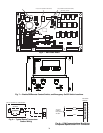
Space temperature sensor wires are to be connected to
terminals in the unit main control box. The space temperature
sensor includes a terminal block (SEN) and a RJ11 female
connector. The RJ11 connector is used access into the Carrier
Comfort Network
®
(CCN) at the sensor.
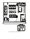
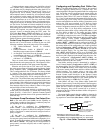
To connect the space temperature sensor (Fig. 8):
1. Using a 20 AWG twisted pair conductor cable rated for
the application, connect 1 wire of the twisted pair to one
SEN terminal and connect the other wire to the other
SEN terminal located under the cover of the space
temperature sensor.
2. Connect the other ends of the wires to terminals 3 and 4
on LVT located in the unit control box.
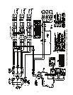
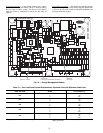
Units on the CCN can be monitored from the space at the
sensor through the RJ11 connector, if desired. To wire the RJ11
connector into the CCN (Fig. 9):
1. Cut the CCN wire and strip ends of the red (+), white
(ground), and black (–) conductors. (If another wire color
scheme is used, strip ends of appropriate wires.)
IMPORTANT: A shorted CCN bus cable will prevent some
routines from running and may prevent the unit from start-
ing. If abnormal conditions occur, unplug the connector. If
conditions return to normal, check the CCN connector and
cable. Run new cable if necessary. A short in one section of
the bus can cause problems with all system elements on the
bus.
THERMISTOR
PIN
CONNECTION
POINT
THERMISTOR INPUT
CLWT J8-13,14 (MBB) Cooler Leaving Fluid
CEWT J8-11,12 (MBB) Cooler Entering Fluid
RGTA
J8-9,10 (MBB) Circuit A Return Gas
Temperature (accessory)
OAT
J8-6,7 (MBB),
LVT 4,13
Outdoor-Air Temperature
Sensor (accessory) or Dual
LWT Sensor
SPT
J8-5,6 (MBB)
LVT-3,4
Accessory Remote Space
Temperature Sensor
CNDE
J8-1,2 Condenser Entering Water
Temperature Sensor
CNDL
J8-3,4 Condenser Leaving Water
Temperature Sensor
LWT — Leaving Water Temperature
MBB — Main Base Board
STATUS SWITCH PIN CONNECTION POINT
Condenser Flow Switch LVT-11,17, J7-2, J6-2
Dual Set Point LVT-12,13, J7-3,4
Remote On/Off LVT-14,15
Cooler Flow Switch Interlock LVT-16,17, J6-2, J7-10
Compressor Fault Signal, A1 J9-11,12
Compressor Fault Signal, A2 J9-5,6
Compressor Fault Signal, A3 J9-8,9
RELAY
NO.
DESCRIPTION
K1 Energize Compressor A1
K2 Energize Compressor A2
K3 Energize Compressor A3
K4 Energize Minimum Load Valve
K5 Water Valve Open
K6 Water Valve Close
K7 Liquid Line Solenoid Valve
K8 Crankcase Heater Relay (30MPA Only)
K9 Chilled Water Pump
K10 Condenser Fan/Pump
K11 Alarm Relay
MANUFACTURER
PART NO.
Regular Wiring Plenum Wiring
Alpha 1895 —
American A21451 A48301
Belden 8205 884421
Columbia D6451 —
Manhattan M13402 M64430
Quabik 6130 —
IMPORTANT: The cable selected for the RJ11 connector
wiring MUST be identical to the CCN communication bus
wire used for the entire network. Refer to Table 18 for
acceptable wiring.