25
Test the condenser output, cooler pump, liquid line solenoid
valve (30MPA only), crankcase heater, water valve (accesso-
ry), and alarm relay by changing the item values from OFF to
ON. These discrete outputs are then turned off if there is no
keypad activity for 10 minutes. When testing compressors,
lead compressor must be started first. All compressor outputs
can be turned on, but the control will limit the rate by staging
one compressor per minute. Minimum load valve can be tested
with the compressors on or off. The relays under the COMP
mode will stay on for 10 minutes if there is no keypad activity.
Compressors will stay on until they are turned off by the opera-
tor. The Service Test mode will remain enabled for as long as
there is one or more compressors running. All safeties are mon-
itored during this test and will turn a compressor, circuit or the
machine off if required. Any other mode or sub-mode can be
accessed, viewed, or changed during the TEST mode. The
STAT item (Run Status
VIEW) will display “0” as long as
the Service mode is enabled. The TEST sub-mode value must
be changed back to OFF before the chiller can be switched to
Enable or Remote contact for normal operation.
Cooler Pump Sequence of Operation — At any-
time the unit is in an ON status, as defined by the one of the
following conditions, the cooler pump relay will be enabled.
1. The Enable-Off-Remote Switch in ENABLE,
(CTRL=0).
2. Enable-Off-Remote Switch in REMOTE with a
Start-Stop remote contact closure (CTRL=0).
3. An Occupied Time Period from an Occupancy Schedule
in combination with items 1 or 2 (CTRL=2).
4. A CCN Start-Stop Command to Start in combination
with items 1 or 2 (CTRL=3).
There are certain alarm conditions and Operating Modes
that will turn the cooler pump relay ON. This sequence will de-
scribe the normal operation of the pump control algorithm.
When the unit cycles from an "On" state to an "Off' state,
the cooler pump output will remain energized for the Cooler
Pump Shutdown Delay (Configuration
OPT1
PM.DY).
This is configurable from 0 to 10 minutes. The factory default
is 1 minute. If the pump output was deenergized during the
transition period, the pump output will not be energized.
The Cooler Pump Relay will be energized when the ma-
chine is "On." The chilled water pump interlock circuit consists
of a chilled water flow switch and a field-installed chilled water
pump interlock. If the chilled water pump interlock circuit does
not close within five (5) minutes of starting, an A200 - Cooler
Flow/Interlock failed to close at Start-Up alam1 will be gener-
ated and chiller will not be allowed to start.
If the chilled water pump interlock or chilled water flow
switch opens for at least three (3) seconds after initially being
closed, an A201 - Cooler Flow 1 Interlock Contacts Opened
During Normal Operation alarm will be generated and the ma-
chine will stop.
Condenser Pump/Condenser Fan Output Con-
trol —
The main base board (MBB) has the capability to
control either a condenser fan output or a condenser pump out-
put depending on the unit configuration.
If the unit is configured for Configuration
UNIT
TYPE = 2 (air cooled), then the output will be off as
long as capacity is equal to 0 and will be energized 5 seconds
before a compressor is started and remain energized until ca-
pacity is 0 again.
If the unit is configured for Configuration
UNIT
TYPE = 3 (water cooled), then the output will be used
for consenser pump control and additional configuration is re-
quired. To enable the condenser pump control use Configura-
tion
OPT1
DPME. The pump can be configured for no
pump control, on when occupied, and on when capacity is
greater than 0.
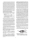
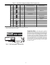
Configuring and Operating Dual Chiller Con-
trol —
The dual chiller routine is available for the control of
two units supplying chilled fluid on a common loop. This
control algorithm is designed for parallel fluid flow arrangement
only. One chiller must be configured as the master chiller, the
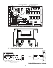
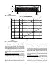
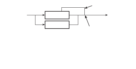
other as the slave. An additional leaving fluid temperature
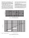
thermistor (Dual Chiller LWT) must be installed as shown in
Fig. 13 and 14 and connected to the master chiller. Refer to Sen-
sors section, page 19, for wiring. The CCN communication bus
must be connected between the two chillers. Connections can be
made to the CCN screw terminals on LVT. Refer to Carrier
Comfort Network
®
Interface section, page 14, for wiring infor-
mation. Configuration examples are shown in Tables 21 and 22.
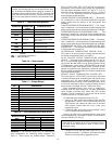
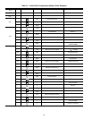
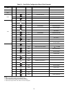
Refer to Table 21 for dual chiller configuration. In this
example the master chiller will be configured at address 1 and
the slave chiller at address 2. The master and slave chillers
must reside on the same CCN bus (Configuration
CCN
CCNB) but cannot have the same CCN address (Configu-
ration
CCN
CCNA). Both master and slave chillers must
have Lead/Lag Chiller Enable (Configuration
RSET
LLEN) configured to ENBL. Master/Slave Select (Config-
uration
RSET
MSSL) must be configured to MAST for
the master chiller and SLVE for the slave. Also in this example,
the master chiller will be configured to use Lead/Lag Balance
Select (Configuration
RSET
LLBL) and Lead/Lag Bal-
ance Delta (Configuration
RSET
LLBD) to even out the
chiller run-times weekly. The Lag Start Delay (Configura-
tion
RSET
LLDY) feature will be set to 10 minutes. This
will prevent the lag chiller from starting until the lead chiller
has been at 100% capacity for the length of the delay time. Par-
allel configuration (Configuration
RSET
PARA) can
only be configured to YES. The variables LLBL, LLBD and
LLDY are not used by the slave chiller.
Dual chiller start/stop control is determined by configura-
tion of Control Method (Configuration
OPT1
CTRL) of
the Master chiller. The Slave chiller should always be config-
ured for CTRL=0 (Switch). If the chillers are to be controlled
by Remote Contacts, both Master and Slave chillers should be
enabled together. Two separate relays or one relay with
two sets of contacts may control the chillers. The Enable/Off/
Remote Contact switch should be in the Remote Contact
position on both the Master and Slave chillers. The Enable/Off/
Remote Contact switch should be in the Enable position for
CTRL=2 (Occupancy) or CTRL=3 (CCN Control).
Both chillers will stop if the Master chiller Enable/Off/
Remote Contact switch is in the Off position. If the Emergency
Stop switch is turned off or an alarm is generated on the Master
chiller the Slave chiller will operate in a Stand-Alone mode.
If the Emergency Stop switch is turned off or an alarm is
generated on the Slave chiller the Master chiller will operate in
a Stand-Alone mode.
The master chiller controls the slave chiller by changing its
Control Mode (Run Status
VIEW
STAT) and its operat-
ing setpoint or Control Point (Run Status
VIEW
CT.PT).
MASTER
CHILLER
SLAVE
CHILLER
LEAVING
FLUID
RETURN
FLUID
THERMISTOR
WIRING*
INSTALL DUAL CHILLER LWT
LEAVING FLUID TEMPERATURE
THERMISTOR (T10) HERE
*Depending on piping sizes, use either:
• HH79NZ014 sensor/10HB50106801 well (3-in. sensor/well)
• HH79NZ029 sensor/10HB50106802 well (4-in. sensor/well)
Fig. 13 — Dual Chiller Thermistor Location


