


39
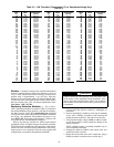
gauge. Pressure readings should be within ± 15 psig. If the
two readings are not reasonably close, replace the pressure
transducer.
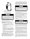
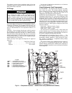
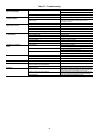
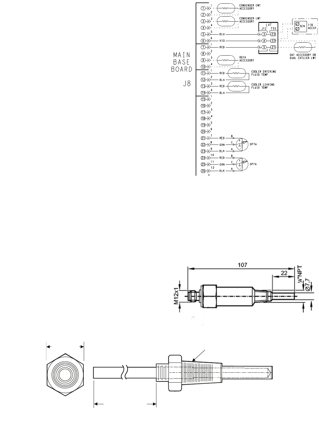
Chilled Water Flow Switch — A factory-installed
flow switch is installed in the leaving fluid piping for all units.
This is a thermal-dispersion flow switch with no field adjust-
ments. The switch is set for approximately 0.5 ft/sec of flow.
The sensor tip houses two thermistors and a heater element.
One thermistor is located in the sensor tip, closest to the flow-
ing fluid. See Fig. 24. This thermistor is used to detect changes
in the flow velocity of the liquid. The second thermistor is
bonded to the cylindrical wall and is affected only by changes
in the temperature of the liquid. The thermistors are positioned
to be in close contact with the wall of the sensor probe and, at
the same time, to be kept separated from each other within the
confines of the probe.
In order to sense flow, it is necessary to heat one of the
thermistors in the probe. When power is applied, the tip of the
probe is heated. As the fluid starts to flow, heat will be carried
away from the sensor tip. Cooling of the first thermistor is a
function of how fast heat is conducted away by the flowing
liquid.
The difference in temperature between the two thermistors
provides a measurement of fluid velocity past the sensor probe.
When fluid velocity is high, more heat will be carried away
from the heated thermistor and the temperature differential will
be small. As fluid velocity decreases, less heat will be taken
from the heated thermistor and there will be an increase in tem-
perature differential.
When unit flow rate is above the minimum flow rate, then
the output is switched on, sending 24 vac to the MBB to prove
flow has been established.
For recommended maintenance, check the sensor tip for
build-up every 6 months. Clean the tip with a soft cloth. If
necessary, build-up (e.g., lime) can be removed with a common
vinegar cleansing agent.
The flow sensor cable is provided with (3) LEDs that indi-
cate if 24 vac power is present and also status of the switch
contacts. The LEDs are as follows:
• Green LED ON – 24 vac present
• One Yellow LED ON – Flow sensor switch OPEN
• Two Yellow LED ON – Flow sensor switch CLOSED
If nuisance trips of the sensor are occurring, follow the
steps below to correct the situation:
1. Check to confirm that the field-installed strainer is clean.
Use the blow-down valve provided or remove the screen
and clean it. For the case of VFD controlled pumps, en-
sure that the minimum speed setting has not been
changed.
2. Measure the pressure drop across the cooler and compare
this to the system requirements.
3. Verify that cable connections at the switch and at the ter-
minal block are secure.
4. Wrong pump motor rotation. Pump must rotate clockwise
when viewed from motor end of pump.
26
25
24
23
22
17
16
15
14
13
12
11
10
9
8
7
6
3
1
3
1
3
1
6
2
4
2
4
2
12
11
21
20
19
18
10
9
8
7
6
5
4
5
4
3
2
1
4
2
1
3
5
BASE
BOARD
J8
SPTA
-
+
DPTA
-
+
A
C
B
A
C
B
RED
GRN
RED
BLK
GRN
RED
BLK
BLU
VIO
LVT
5
4
3
22
23
21
T-55
ACCSY
SEN
OAT ACCESSORY OR
DUAL CHILLER LWT
CONDENSER EWT
ACCESSORY
CONDENSER LWT
ACCESSORY
BLK
RED
COOLER ENTERING
FLUID TEMP
BLK
RED
COOLER LEAVING
FLUID TEMP
RGTA
ACCESSORY
J12 T55
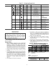
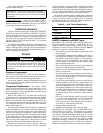
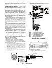
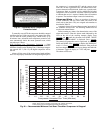
Fig. 23 — Thermistor Connections to
Main Base Board, J8 Connector
LEGEND
ACCSY — Accessory
DPT — Discharge Pressure Transducer
EWT — Entering Water Temperature
LWT — Leaving Water Temperature Sensor
LVT — Low Voltage Terminal
OAT — Outdoor Air Temperature Sensor
RGT — Return Gas Temperature Sensor
SEN — Sensor Terminal Block
SPT — Space Temperature Sensor
a30-5043
Fig. 24— Chilled Water Flow Switch
a30-499
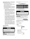
NOTE: Dimensions are in millimeters.
5/8 in. HEX
6" MINIMUM
CLEARANCE FOR
THERMISTOR
REMOVAL
1/4-18 NPT
Fig. 22 — Thermistor Well