


43
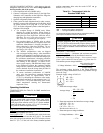
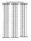
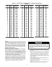
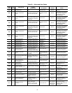
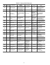
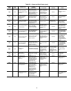
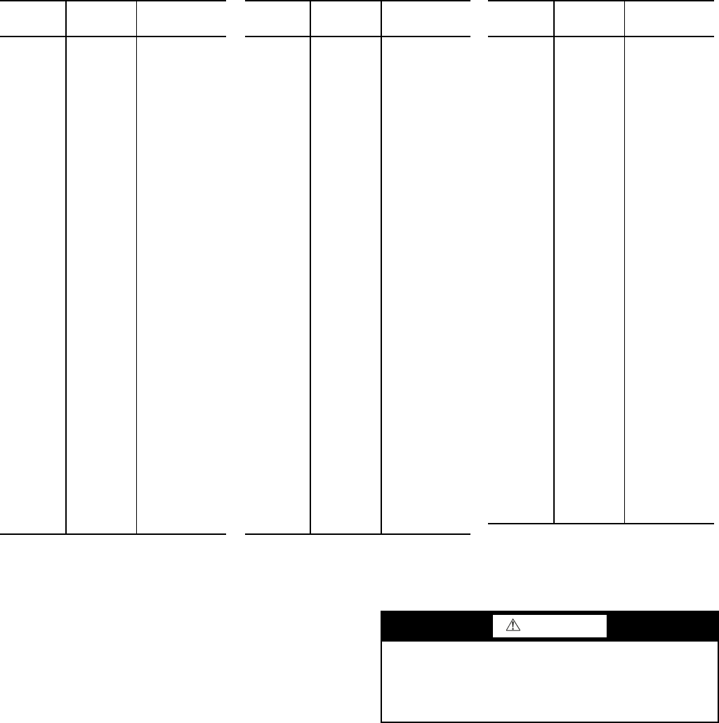
Table 35 — 10K Thermistor Temperature (°C) vs. Resistance/Voltage Drop
(For SPT)
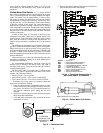
Strainer — Periodic cleaning of the required field-installed
strainer is required. Pressure drop across strainer in excess of
3 psi (21 kPa) indicates the need for cleaning. Normal (clean)
pressure drop is approximately 1 psi (6.9 kPa). Open the
blowdown valve to clean the strainer. If required, shut the chill-
er down and remove the strainer screen to clean. When strainer
has been cleaned, enter ‘YES’ for Strainer Maintenance Done
(Run Status
PM
S.T.MN.
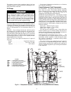
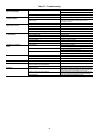
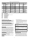
Replacing Defective Modules — The Comfort-
Link
™
replacement modules are shown in Table 36. If the main
base board (MBB) has been replaced, verify that all configura-
tion data is correct. Follow the Configuration mode table and
verify that all items under sub-modes UNIT, OPT1 and OPT2
are correct. Any additional field-installed accessories or op-
tions (RSET, SLCT sub-modes) should also be verified as well
as any specific time and maintenance schedules.
Refer to the Start-Up Checklist for 30MP Liquid Chillers
(completed at time of original start-up) found in the job folder.
This information is needed later in this procedure. If the check-
list does not exist, fill out the current information in the Config-
uration mode on a new checklist. Tailor the various options and
configurations as needed for this particular installation.
1. Check that all power to unit is off. Carefully disconnect
all wires from the defective module by unplugging its
connectors.
2. Remove the defective module by removing its mounting
screws with a Phillips screwdriver, and removing the
module from the control box. Save the screws later use.
3. Verify that the instance jumper (MBB) or address switch-
es (all other modules) exactly match the settings of the
defective module.
NOTE: Handle boards by mounting standoffs only to
avoid electrostatic discharge.
4. Package the defective module in the carton of the new
module for return to Carrier.
5. Mount the new module in the unit’s control box using a
Phillips screwdriver and the screws saved in Step 2.
TEMP
(C)
VOLTAGE
DROP
(V)
RESISTANCE
(Ohms)
–32 4.762 200,510
–31 4.748 188,340
–30 4.733 177,000
–29 4.716 166,342
–28 4.700 156,404
–27 4.682 147,134
–26 4.663 138,482
–25 4.644 130,402
–24 4.624 122,807
–23 4.602 115,710
–22 4.580 109,075
–21 4.557 102,868
–20 4.533 97,060
–19 4.508 91,588
–18 4.482 86,463
–17 4.455 81,662
–16 4.426 77,162
–15 4.397 72,940
–14 4.367 68,957
–13 4.335 65,219
–12 4.303 61,711
–11 4.269 58,415
–10 4.235 55,319
–9 4.199 52,392
–8 4.162 49,640
–7 4.124 47,052
–6 4.085 44,617
–5 4.044 42,324
–4 4.003 40,153
–3 3.961 38,109
–2 3.917 36,182
–1 3.873 34,367
0 3.828 32,654
1 3.781 31,030
2 3.734 29,498
3 3.686 28,052
4 3.637 26,686
5 3.587 25,396
6 3.537 24,171
7 3.485 23,013
8 3.433 21,918
9 3.381 20,883
10 3.328 19,903
11 3.274 18,972
12 3.220 18,090
13 3.165 17,255
14 3.111 16,464
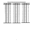
TEMP
(C)
VOLTAGE
DROP
(V)
RESISTANCE
(Ohms)
15 3.056 15,714
16 3.000 15,000
17 2.944 14,323
18 2.889 13,681
19 2.833 13,071
20 2.777 12,493
21 2.721 11,942
22 2.666 11,418
23 2.610 10,921
24 2.555 10,449
25 2.500 10,000
26 2.445 9,571
27 2.391 9,164
28 2.337 8,776
29 2.284 8,407
30 2.231 8,056
31 2.178 7,720
32 2.127 7,401
33 2.075 7,096
34 2.025 6,806
35 1.975 6,530
36 1.926 6,266
37 1.878 6,014
38 1.830 5,774
39 1.784 5,546
40 1.738 5,327
41 1.692 5,117
42 1.648 4,918
43 1.605 4,727
44 1.562 4,544
45 1.521 4,370
46 1.480 4,203
47 1.439 4,042
48 1.400 3,889
49 1.362 3,743
50 1.324 3,603
51 1.288 3,469
52 1.252 3,340
53 1.217 3,217
54 1.183 3,099
55 1.150 2,986
56 1.117 2,878
57 1.086 2,774
58 1.055 2,675
59 1.025 2,579
60 0.996 2,488
61 0.968 2,400
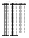
TEMP
(C)
VOLTAGE
DROP
(V)
RESISTANCE
(Ohms)
62 0.940 2,315
63 0.913 2,235
64 0.887 2,157
65 0.862 2,083
66 0.837 2,011
67 0.813 1,943
68 0.790 1,876
69 0.767 1,813
70 0.745 1,752
71 0.724 1,693
72 0.703 1,637
73 0.683 1,582
74 0.663 1,530
75 0.645 1,480
76 0.626 1,431
77 0.608 1,385
78 0.591 1,340
79 0.574 1,297
80 0.558 1,255
81 0.542 1,215
82 0.527 1,177
83 0.512 1,140
84 0.497 1,104
85 0.483 1,070
86 0.470 1,037
87 0.457 1,005
88 0.444 974
89 0.431 944
90 0.419 915
91 0.408 889
92 0.396 861
93 0.386 836
94 0.375 811
95 0.365 787
96 0.355 764
97 0.345 742
98 0.336 721
99 0.327 700
100 0.318 680
101 0.310 661
102 0.302 643
103 0.294 626
104 0.287 609
105 0.279 592
106 0.272 576
107 0.265 561
WARNING
Electrical shock can cause personal injury and death. Shut
off all power to this equipment during installation. There
may be more than one disconnect switch. Tag all discon-
nect locations to alert others not to restore power until work
is completed.