


33
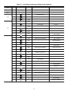
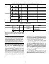
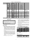
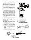
Table 27 — Configuring Demand Limit
*Seven items skipped in this example.
PRE-START-UP
Do not attempt to start the chiller until following checks
have been completed.
System Check
1. Check all auxiliary components, such as chilled fluid
pumps, air-handling equipment, condenser pump or other
equipment to which the chiller supplies liquid. Consult
manufacturer's instructions. Verify that any pump inter-
lock contacts have been properly installed. If the unit has
field-installed accessories, be sure all are properly in-
stalled and wired correctly. Refer to unit wiring diagrams.
2. Use the scrolling marquee display to adjust the Cooling
Set Point.
3. Fill chilled fluid circuit with clean water (with recom-
mended inhibitor added) or other non-corrosive fluid to
be cooled. Bleed all air out of the high points of the sys-
tem. If chilled water is to be maintained at a temperature
below 40 F (4.4 C), a brine of sufficient concentration
must be used to prevent freeze-up at anticipated suction
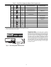
temperatures. To ensure sufficient loop volume, see
Table 28.
4. Check tightness of all electrical connections.
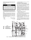
5. Oil should be visible in the compressor sightglass(es).
See Fig. 20. An acceptable oil level in the compressors is
from
1
/
8
to
3
/
8
of sight glass when the compressors are off.
Adjust the oil level as required. See Oil Charge section on
page 37 for Carrier approved oils.
6. Crankcase heaters must be firmly attached to compres-
sors, and must be on for 24 hours prior to start-up
(30MPA units only).
7. Electrical power source must agree with unit nameplate.
8. Check rotation of scroll compressors. Monitor control
alarms during first compressor start up for reverse rota-
tion protection alarm.
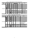
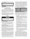
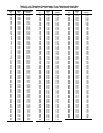
Table 28 — Minimum Flow Rates and Minimum
Loop Volume (for Comfort Cooling)
LEGEND
NOTES:
Gallons = V x AHRI capacity in tons.
Liters = N x AHRI capacity in kW.
MODE
KEYPAD
ENTRY
SUB-MODE
KEYPAD
ENTRY
ITEM DISPLAY ITEM EXPANSION COMMENT
CONFIGURATION
DISP TEST ON/OFF Test Display LEDs
UNIT TYPE X Unit Type
OPT1 FLUD X Cooler Fluid
OPT2 CTRL X Control Method
CCN
CCNA X CCN Address
RSET CRST X Cooling Reset Type
DMDC* X Demand Limit Select
Default: 0
0 = None
1 = Switch
2 = 4 to 20 mA Input
3 = CCN Loadshed
DM20 XXX % Demand Limit at 20 mA
Default: 100%
Range: 0 to 100
SHNM XXX
Loadshed Group
Number
Default: 0
Range: 0 to 99
SHDL XXX%
Loadshed Demand
Delta
Default: 0%
Range: 0 to 60%
SHTM XXX MIN
Maximum Loadshed
Time
Default: 60 min.
Range: 0 to 120 min.
DLS1 XXX %
Demand Limit
Switch 1
Default: 80%
Range: 0 to 100%
DLS2 XXX %
Demand Limit
Switch 2
Default: 50%
Range: 0 to 100%
ENTER
ENTER
ENTER
ENTER
ENTER
ENTER
ENTER
IMPORTANT: Before beginning Pre-Start-Up or Start-Up,
complete Start-Up Checklist for 30MP Liquid Chiller at
end of this publication (page CL-1 to CL-8). The checklist
assures proper start-up of a unit, and provides a record of
unit condition, application requirements, system informa-
tion, and operation at initial start-up.
UNIT SIZE
EVAPORATOR CONDENSER*
MINIMUM EVAPORATOR
LOOP VOLUME
Gal./Min L/s Gal./Min L/s Gal. L
30MP015 22 1.4 22 1.4 46.2 174.9
30MP020 28 1.8 28 1.8 60.9 230.5
30MP030 43 2.7 43 2.7 92.4 349.7
30MP040 55 3.5 55 3.5 78.4 296.7
30MP045 64 4.0 64 4.0 91.6 346.7
AHRI — Air Conditioning, Heating, and Refrigeration Institute
N—Liters per kW
V—Gallons per ton
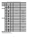
APPLICATION V N
Normal Air Conditioning 33.25
Process Type Cooling 6 to 10 6.5 to 10.8
Low Ambient Operation 6 to 10 6.5 to 10.8