


2
CONTENTS
Page
SAFETY CONSIDERATIONS. . . . . . . . . . . . . . . . . . . . . . . . . 1
GENERAL. . . . . . . . . . . . . . . . . . . . . . . . . . . . . . . . . . . . . . . . 2-13
Conventions Used in this Manual . . . . . . . . . . . . . . . . . . . 2
Basic Controls Usage. . . . . . . . . . . . . . . . . . . . . . . . . . . . . . . 3
CONTROLS . . . . . . . . . . . . . . . . . . . . . . . . . . . . . . . . . . . . . 14-33
General . . . . . . . . . . . . . . . . . . . . . . . . . . . . . . . . . . . . . . . . . . . . 14
Main Base Board (MBB). . . . . . . . . . . . . . . . . . . . . . . . . . . . 14
Energy Management Module (EMM). . . . . . . . . . . . . . . . 14
Current Sensor Board (CSB) . . . . . . . . . . . . . . . . . . . . . . . 14
Enable/Off/Remote Contact Switch. . . . . . . . . . . . . . . . . 14
Emergency On/Off Switch. . . . . . . . . . . . . . . . . . . . . . . . . . 14
Board Addresses . . . . . . . . . . . . . . . . . . . . . . . . . . . . . . . . . . 14
Control Module Communication . . . . . . . . . . . . . . . . . . . 14
Carrier Comfort Network
®
Interface . . . . . . . . . . . . . . . . 14
Sensors. . . . . . . . . . . . . . . . . . . . . . . . . . . . . . . . . . . . . . . . . . . . 19
• COOLER LEAVING FLUID SENSOR
• COOLER ENTERING FLUID SENSOR
• CONDENSER LEAVING FLUID SENSOR
• CONDENSER ENTERING FLUID SENSOR
• COMPRESSOR RETURN GAS
TEMPERATURE SENSOR
• OUTDOOR-AIR TEMPERATURE SENSOR
• DUAL LEAVING WATER TEMPERATURE SENSOR
• REMOTE SPACE TEMPERATURE SENSOR
Energy Management Module. . . . . . . . . . . . . . . . . . . . . . . 21
Loss-of-Cooler Flow Protection . . . . . . . . . . . . . . . . . . . . 21
Condenser Flow Protection . . . . . . . . . . . . . . . . . . . . . . . . 21
Thermostatic Expansion Valves (TXV) . . . . . . . . . . . . . 21
Capacity Control. . . . . . . . . . . . . . . . . . . . . . . . . . . . . . . . . . . 21
• MINUTES LEFT FOR START
• MINUTES OFF TIME
• LEAD/LAG DETERMINATION
• CAPACITY CONTROL OVERRIDES
Operation of Machine Based on Control Method
and Cooling Set Point Selection Settings . . . . . . . . 24
Cooling Set Point Select . . . . . . . . . . . . . . . . . . . . . . . . . . . 24
Cooler Pump Control . . . . . . . . . . . . . . . . . . . . . . . . . . . . . . 24
Ice Mode . . . . . . . . . . . . . . . . . . . . . . . . . . . . . . . . . . . . . . . . . . . 24
Service Test. . . . . . . . . . . . . . . . . . . . . . . . . . . . . . . . . . . . . . . . 24
Cooler Pump Sequence of Operation . . . . . . . . . . . . . . 25
Condenser Pump/Condenser Fan Output
Control . . . . . . . . . . . . . . . . . . . . . . . . . . . . . . . . . . . . . . . . 25
Configuring and Operating Dual Chiller Control. . . . 25
Temperature Reset. . . . . . . . . . . . . . . . . . . . . . . . . . . . . . . . . 27
Demand Limit . . . . . . . . . . . . . . . . . . . . . . . . . . . . . . . . . . . . . . 31
• DEMAND LIMIT (2-Stage Switch Controlled)
• EXTERNALLY POWERED DEMAND LIMIT
(4 to 20 mA Controlled)
• DEMAND LIMIT (CCN Loadshed Controlled)
Cooling Set Point (4 to 20 mA) . . . . . . . . . . . . . . . . . . . . . 32
PRE-START-UP. . . . . . . . . . . . . . . . . . . . . . . . . . . . . . . . . . .33,34
System Check . . . . . . . . . . . . . . . . . . . . . . . . . . . . . . . . . . . . . 33
START-UP AND OPERATION . . . . . . . . . . . . . . . . . . . . 34-36
Actual Start-Up . . . . . . . . . . . . . . . . . . . . . . . . . . . . . . . . . . . . 34
Check Refrigerant Charge. . . . . . . . . . . . . . . . . . . . . . . . . . 34
Operating Limitations. . . . . . . . . . . . . . . . . . . . . . . . . . . . . . 35
• TEMPERATURES
• VOLTAGE — ALL UNITS
OPERATION SEQUENCE . . . . . . . . . . . . . . . . . . . . . . . . 36
SERVICE . . . . . . . . . . . . . . . . . . . . . . . . . . . . . . . . . . . . . 36-44
Electronic Components. . . . . . . . . . . . . . . . . . . . . . . . . . . . 36
• CONTROL COMPONENTS
Compressor Replacement . . . . . . . . . . . . . . . . . . . . . . . . . 36
30MPW Condenser and 30MP Cooler . . . . . . . . . . . . . . 36
• BRAZED-PLATE COOLER AND CONDENSER
HEAT EXCHANGER REPLACEMENT
• BRAZED-PLATE COOLER AND CONDENSER
HEAT EXCHANGER CLEANING
Oil Charge . . . . . . . . . . . . . . . . . . . . . . . . . . . . . . . . . . . . . . . . . 37
Check Refrigerant Feed Components . . . . . . . . . . . . . . 37
• FILTER DRIER
• MOISTURE-LIQUID INDICATOR
• THERMOSTATIC EXPANSION VALVE (TXV)
• MINIMUM LOAD VALVE
• PRESSURE RELIEF DEVICES
Check Unit Safeties. . . . . . . . . . . . . . . . . . . . . . . . . . . . . . . . 38
Thermistors. . . . . . . . . . . . . . . . . . . . . . . . . . . . . . . . . . . . . . . . 38
Pressure Transducers . . . . . . . . . . . . . . . . . . . . . . . . . . . . . 38
Chilled Water Flow Switch . . . . . . . . . . . . . . . . . . . . . . . . . 39
Strainer. . . . . . . . . . . . . . . . . . . . . . . . . . . . . . . . . . . . . . . . . . . . 43
Replacing Defective Modules. . . . . . . . . . . . . . . . . . . . 43
MAINTENANCE . . . . . . . . . . . . . . . . . . . . . . . . . . . . . . . . . .44,45
Recommended Maintenance Schedule . . . . . . . . . . . . 44
TROUBLESHOOTING . . . . . . . . . . . . . . . . . . . . . . . . . . . .44-52
Complete Unit Stoppage and Restart . . . . . . . . . . . . . . 44
• GENERAL POWER FAILURE
• UNIT ENABLE-OFF-REMOTE CONTACT SWITCH IS
OFF
• CHILLED FLUID PROOF-OF-FLOW SWITCH OPEN
• OPEN 24-V CONTROL CIRCUIT BREAKERS
• COOLING LOAD SATISFIED
• THERMISTOR FAILURE
• LOW SATURATED SUCTION
• COMPRESSOR SAFETIES
Alarms and Alerts . . . . . . . . . . . . . . . . . . . . . . . . . . . . . . . . . 45
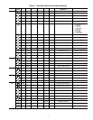
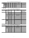
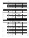
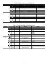
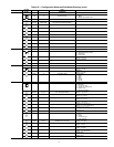
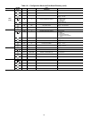
APPENDIX A — LOCAL DISPLAY TABLES . . . . . . .53-64
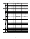
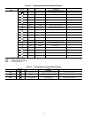
APPENDIX B — CCN TABLES. . . . . . . . . . . . . . . . . . . .65-72
START-UP CHECKLIST FOR 30MP LIQUID
CHILLER
. . . . . . . . . . . . . . . . . . . . . . . . . . . . . .CL-1 to CL-8
GENERAL
This publication contains Start-Up, Service, Controls, Oper-
ation, and Troubleshooting information for the 30MPW water-
cooled chillers and the 30MPA air-cooled chillers. See Table 1.
These liquid chillers are equipped with ComfortLink controls
and conventional thermostatic expansion valves (TXVs). The
30MPA units and the 30MPW units with optional medium
temperature brine are also equipped with liquid line solenoid
valves (LLSVs).
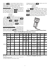
Table 1 — Unit Sizes
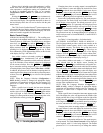
Conventions Used in This Manual — The follow-
ing conventions for discussing configuration points for the
local display (scrolling marquee or Navigator™ accessory)
will be used in this manual.
Point names will be written with the mode name first, then
any sub-modes, then the point name, each separated by an
arrow symbol (. Names will also be shown in bold
and italics. As an example, the Minimum Load Valve Select
Point, which is located in the Configuration mode, Option 1
sub-mode, would be written as ConfigurationOPT1
MLV.S.
This path name will show the user how to navigate through
the local display to reach the desired configuration. The user
would scroll through the modes and sub-modes using the
and keys. The arrow symbol in the path name
represents pressing to move into the next level of the
menu structure.
CAUTION
This unit uses a microprocessor-based electronic control
system. Do not use jumpers or other tools to short out or
bypass components or otherwise depart from recom-
mended procedures. Any short-to-ground of the control
board or accompanying wiring may destroy the board or
electrical component.
UNIT MODEL NOMINAL TONS
30MPA,MPW015 15
30MPA,MPW020 20
30MPA,MPW030 30
30MPA,MPW040 40
30MPA,MPW045 45
ENTER