


52
This is done to make a rough calibration of the high pres-
sure switch trip point. In most cases this allows the control to
detect a high head pressure condition prior to reaching the high
pressure switch trip point.
When the trip occurs, all mechanical cooling on the circuit
is shut down for 15 minutes. After 15 minutes, the circuit is al-
lowed to restart.
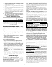
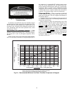
A126 (Circuit A High Head Pressure)
— This alarm occurs
when the appropriate saturated condensing temperature is
greater than the operating envelope shown in Fig 12. Prior to
the alarm, the control will shut down one compressor on a cir-
cuit if that circuit's saturated condensing temperature is greater
than the maximum SCT minus 5° F (2.7° C). If SCT continues
to rise to greater than the maximum SCT, the alarm will occur
and the circuit's remaining compressor will shut down. The
cause of the alarm is usually an overcharged system, high out-
door ambient temperature coupled with dirty outdoor coil
(30MPA only), plugged filter drier, a faulty high-pressure
switch, or loss of condenser water flow.
A140 (Reverse Rotation Detected)
— A test is made once, on
power up, for suction pressure change on the first activated cir-
cuit. The unit control determines failure as follows:
1. The suction pressure is sampled 5 seconds before the
compressor is brought on, right when the compressor is
brought on and 5 seconds afterwards.
2. The rate of suction pressure change from 5 seconds be-
fore the compressor is brought on to when the compres-
sor is brought on is calculated.
3. The rate of suction pressure change from when the
compressor is brought on to 5 seconds afterwards is
calculated.
4. With the above information, the test for reverse rotation is
made. If the suction pressure change 5 seconds after com-
pression is greater than the suction pressure change 5 sec-
onds before compression – 1.25, then there is a reverse
rotation error.
This alarm will disable mechanical cooling and will require
manual reset. This alarm may be disabled once the reverse ro-
tation check has been verified by setting REV.R = Yes.
A150 (Unit is in Emergency Stop)
— If the CCN emergency
stop command is received, the alarm is generated and the unit
will be immediately stopped.
If the CCN point name "EMSTOP" in the system table is set
to emergency stop, the unit will shut down immediately and
broadcast an alarm back to the CCN, indicating that the unit is
down. This alarm will clear when the variable is set back to
"enable."
A151 (Illegal Configuration)
— An A151 alarm indicates an
invalid configuration has been entered. The following are ille-
gal configurations.
• Invalid unit size has been entered.
• Unit configuration set to invalid type.
A152 (Unit Down Due to Failure)
— Reset is automatic
when all alarms are cleared. This alarm indicates the unit is at
0% capacity.
T153 (Real Time Clock Hardware Failure)
— A problem
has been detected with MBB real time clock hardware. Try re-
setting the power and check the indicator lights. If the alarm
continues, the board should be replaced.
A154 (Serial EEPROM Hardware Failure)
— A problem
has been detected with the EEPROM on the MBB. Try
resetting the power and check the indicator lights. If the alarm
continues, the board should be replaced.
T155 (Serial EEPROM Storage Failure Error)
— A problem
has been detected with the EEPROM storage on the MBB. Try
resetting the power and check the indicator lights. If the alert
continues, the board should be replaced.
A156 (Critical Serial EEPROM Storage Failure Error)
— A
problem has been detected with the EEPROM storage on the
MBB. Try resetting the power and check the indicator lights. If
the alarm continues, the board should be replaced.
A157 (A/D Hardware Failure)
— A problem has been detect-
ed with A/D conversion on the boards. Try resetting the power
and check the indicator lights. If the alarm continues, the board
should be replaced.
T173 (Energy Management Module Communication Fail-
ure) — This alert indicates that there are communications
problems with the energy management. All functions per-
formed by the EMM will stop, which can include demand lim-
it, reset and capacity input. The alert will automatically reset.
T174 (4 to 20 mA Cooling Set point Input Failure)
— This
alert indicates a problem has been detected with cooling set
point 4 to 20 mA input. The input value is either less than 2 mA
or greater than 22 mA.
T176 (4 to 20 mA Reset Input Failure)
— This alert indi-
cates a problem has been detected with reset 4 to 20 mA input.
The input value is either less than 2 mA or greater than 22 mA.
The reset function will be disabled when this occurs.
T177 (4 to 20 mA Demand Limit Input Failure)
— This
alert indicates a problem has been detected with demand limit
4 to 20 mA input. The input value is either less than 2 mA or
greater than 22 mA. The reset function will be disabled when
this occurs.
T500, T501, T502 (Current Sensor Board Failure — A xx
Circuit A — Alert codes 500, 501, and 502 are for compres-
sors A1, A2, and A3 respectively. These alerts occur when the
output of the CSB is a constant high value. These alerts reset
automatically. If the problem cannot be resolved, the CSB must
be replaced.