


27
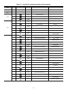
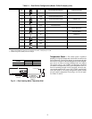
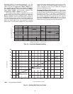
Table 21 — Dual Chiller Configuration (Master Chiller Example) (cont)
NOTES:
1. Master Control Method (CTRL) can be configured as 0-Switch, 2-Occupancy or 3-CCN.
2. Parallel Configuration (PARA) cannot be changed.
Temperature Reset — The control system is capable of
handling leaving-fluid temperature reset based on return cooler
fluid temperature. Because the change in temperature through
the cooler is a measure of the building load, the return tempera-
ture reset is in effect an average building load reset method.
The control system is also capable of temperature reset based
on outdoor-air temperature (OAT), space temperature (SPT), or
from an externally powered 4 to 20 mA signal. Accessory sen-
sors must be used for SPT reset (33ZCT55SPT) and for OAT
reset (HH79NZ014). The energy management module (EMM)
must be used for temperature reset using a 4 to 20 mA signal.
See Tables 23 and 24.
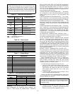
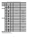
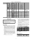
SUB-MODE ITEM KEYPAD ENTRY DISPLAY ITEM EXPANSION COMMENTS
RSET
LLBL 2 LEAD/LAG BALANCE SELECT CHANGE ACCEPTED
LLBL
LLBD LEAD/LAG BALANCE DELTA
LLBD 168 LEAD/LAG BALANCE DELTA DEFAULT 168
LLBD
LLDY LAG START DELAY
LLDY 5 SCROLLING STOPS
5 VALUE FLASHES
10 SELECT 10
LLDY 10 LAG START DELAY CHANGE ACCEPTED
LLDY
RSET
PARA YES MASTER COMPLETE
ENTER
ESCAPE
ENTER
ESCAPE
ENTER
ENTER
ENTER
ESCAPE
ESCAPE
ENTER
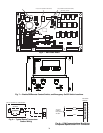
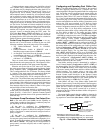
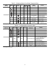
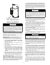
A
B
1/4 N.P.T.
0.505/0.495
0.61
DIA
6” MINIMUM
CLEARANCE FOR
THERMISTOR
REMOVAL
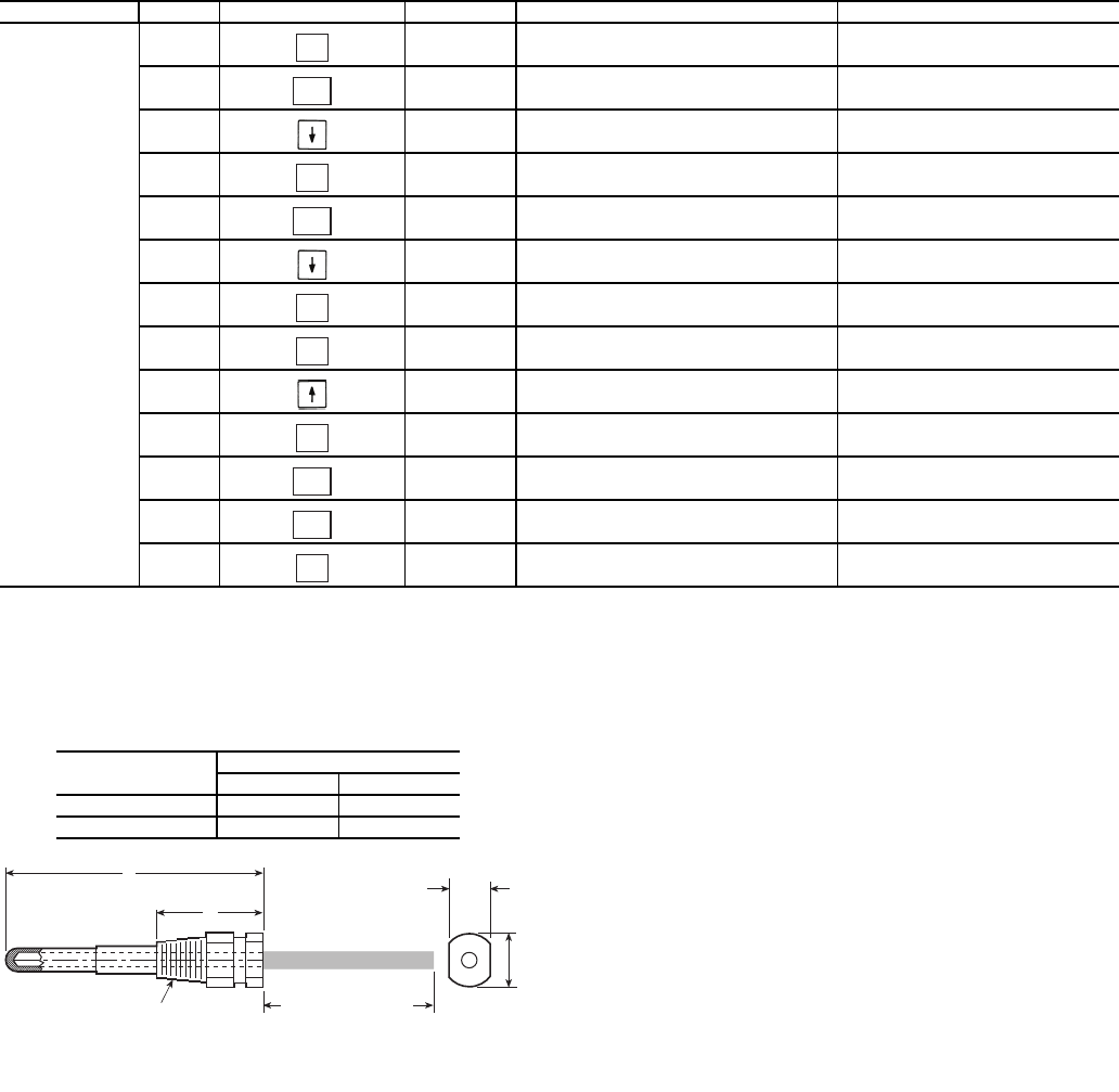
Fig. 14 — Dual Leaving Water Thermistor Well
PART
NUMBER
DIMENSIONS in. (mm)
A B
10HB50106801 3.10 (78.7) 1.55 (39.4)
10HB50106802 4.10 (104.1) 1.28 (32.5)