


35
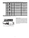
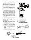
LIQUID CHARGING METHOD — Add charge to the unit
through the liquid line service valve. Never charge liquid into
the low-pressure side of the system.
1. Close liquid line ball valve (30MPA only).
2. Connect a refrigerant cylinder loosely to the high flow
Schraeder valve connection on the liquid line. Purge the
charging hose and tighten the connections.
3. Open the refrigerant cylinder valve.
4. If the system has been dehydrated and is under vacuum,
break the vacuum with refrigerant gas. For R-410A, build
up system pressure to 101 psig and 32 F (697 kPa and
0° C). Invert the refrigerant cylinder so that the liquid re-
frigerant will be charged.
5. a. For complete charge of 30MPW units, follow
charging by weight procedure. When charge is
nearly full, complete the process by observing the
sight glass for clear liquid flow while the unit is
operating. The use of sight glass charging is valid
only when unit is operating at full capacity.
b. For complete charge of 30MPA units or where
refrigerant cylinder cannot be weighed, follow the
condenser manufacturer’s charging procedure or
follow charging by sight glass procedure. The use
of sight glass charging is valid only when unit is
operating at full capacity.
6. a. The 30MPA condenserless units are shipped
with a nitrogen holding charge. After installation
with the field-supplied system high side, the com-
plete system should be evacuated and charged per
the condenser manufacturer’s charging procedure
or charged until the sight glass is clear (with the
unit running at full capacity). To achieve maxi-
mum system capacity, add additional charge equal
to the difference between the condenser optimal
charge and the condenser minimum charge, which
can be obtained from the charge data provided in
the condenser installation instructions.
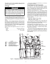
b. To ensure maximum performance of 30MPW
units, raise the compressor saturated discharge
temperature (SDT) to approximately 100 F
(37.8 C) by throttling the condenser water intake.
Add charge until there is approximately 9 to 12° F
(5.0 to 6.6° C) of system subcooling (SDT minus
actual temperature entering the thermostatic
expansion valve).
Operating Limitations
TEMPERATURES (See Table 29 for 30MP standard tem-
perature limits).
High Cooler Leaving Chilled Water (Fluid) Temperatures
(LCWT) — During start-up with cooler the LCWT should not
be above approximately 60 F (16 C).
Low Cooler LCWT
— For standard units with fresh water,
the LCWT must be no lower than 40 F (4.4 C). For standard
units with a proper brine solution, the LCWT must be no lower
than 32 F (0° C). If the unit is the factory-installed optional
medium temperature brine unit, the cooler LCWT can go
down to 15 F (–9.4 C).
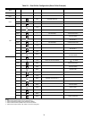
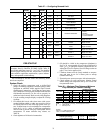
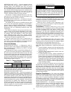
Table 29 — Temperature Limits for
Standard 30MP Units
LEGEND
*For sustained operation, EWT should not exceed 85 F (29.4 C).
†Unit requires modification below this temperature.
VOLTAGE — ALL UNITS
Main Power Supply
— Minimum and maximum acceptable
supply voltages are listed in the Installation Instructions.
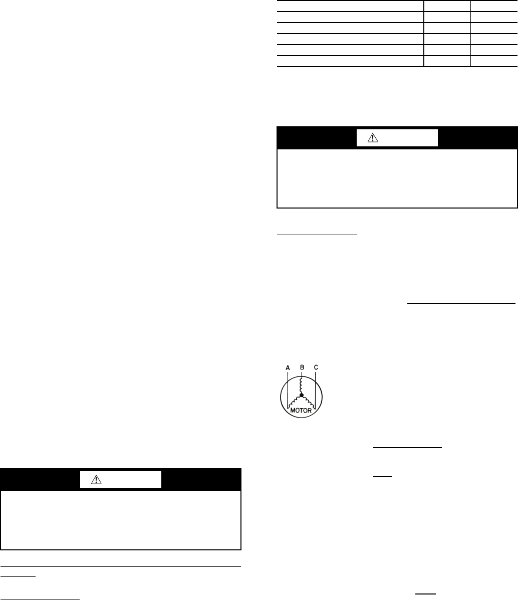
Unbalanced 3-Phase Supply Voltage — Never operate a motor
where a phase imbalance between phases is greater than 2%.
To determine percent voltage imbalance:
The maximum voltage deviation is the largest difference
between a voltage measurement across 2 legs and the average
across all 3 legs.
Example: Supply voltage is 240-3-60.
AB = 243 v
BC = 236 v
AC = 238 v
1. Determine average voltage:
2. Determine maximum deviation from average voltage:
(AB) 243 – 239 = 4 v
(BC) 239 – 236 = 3 v
(AC) 239 – 238 = 1 v
Maximum deviation is 4 v.
3. Determine percent voltage imbalance:
CAUTION
Do not operate with cooler leaving chiller water (fluid)
temperature (LCWT) below 32 F (0° C) for standard units
with proper brine solution or 40 F (4.4 C) for the standard
units with fresh water, or below 15 F (–9.4 C) for units fac-
tory built for medium temperature brine.
TEMPERATURE LIMIT F C
Maximum Condenser LWT
140 60
Minimum Condenser EWT
70 21
Maximum Cooler EWT*
95 35
Maximum Cooler LWT
70 21
Minimum Cooler LWT†
40 4
EWT —
Entering Fluid (Water) Temperature
LWT —
Leaving Fluid (Water) Temperature
CAUTION
Medium temperature brine duty application (below 32 F
[0° C] LCWT) for chiller normally requires factory modifi-
cation. Contact your Carrier representative for applicable
LCWT range for standard water-cooled chiller in a specific
application.
% Voltage Imbalance = 100 x
max voltage deviation
from avg voltage
average voltage
Average voltage =
243 + 236 + 238
3
=
717
3
= 239
% Voltage Imbalance = 100 x
4
239
= 1.7%
a30-4979