


44
6. Reinstall all module connectors. For accessory Naviga-
tor™ device replacement, make sure the plug is installed
at TB3 in the LEN connector.
7. Carefully check all wiring connections before restoring
power.
8. Verify the ENABLE/OFF/REMOTE CONTACT switch
is in the OFF position.
9. Restore control power. Verify that all module red LEDs
blink in unison. Verify that all green LEDs are blinking
and that the scrolling marquee or Navigator™ display is
communicating correctly.
10. Verify all configuration information, settings, set points
and schedules. Return the ENABLE/OFF/REMOTE
CONTACT switch to its previous position.
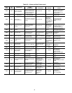
Table 36 — Replacement Modules
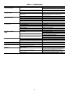
MAINTENANCE
Recommended Maintenance Schedule —
The fol-
lowing are only recommended guidelines. Jobsite conditions
may dictate that maintenance schedule is performed more often
than recommended.
Routine:
Every month:
• Check moisture indicating sight glass for possible refrig-
erant loss and presence of moisture.
Every 3 months (for all machines):
• Check refrigerant charge.
• Check all refrigerant joints and valves for refrigerant
leaks, repair as necessary.
• Check chilled water flow switch operation.
• Check compressor oil level.
Every 12 months (for all machines):
• Check all electrical connections, tighten as necessary.
• Inspect all contactors and relays, replace as necessary.
• Check accuracy of thermistors, replace if greater than
± 2° F (1.2° C) variance from calibrated thermometer.
• Check to be sure that the proper concentration of anti-
freeze is present in the chilled water loop, if applicable.
• Verify that the chilled water loop is properly treated.
• Check refrigerant filter driers for excessive pressure
drop, replace as necessary.
• Check chilled water and condenser strainers, clean as
necessary.
• Perform Service Test to confirm operation of all
components.
• Check for excessive cooler approach (Leaving Chilled
Water Temperature — Saturated Suction Temperature)
which may indicate fouling. Clean evaporator if
necessary.
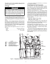
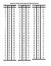
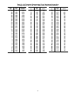
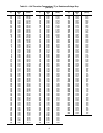
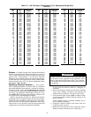
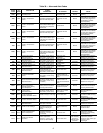
TROUBLESHOOTING
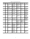
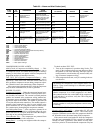
Complete Unit Stoppage and Restart —
Possi-
ble causes for unit stoppage and reset methods are shown be-
low and in Table 37. Refer to Fig. 3-7 for component arrange-
ment and control wiring diagrams.
GENERAL POWER FAILURE — After power is restored,
restart is automatic through normal MBB start-up.
UNIT ENABLE-OFF-REMOTE CONTACT SWITCH IS
OFF — When the switch is OFF, the unit will stop immediate-
ly. Place the switch in the ENABLE position for local switch
control or in the REMOTE CONTACT position for control
through remote contact closure.
CHILLED FLUID PROOF-OF-FLOW SWITCH OPEN —
After the problem causing the loss of flow has been corrected,
reset is manual by resetting the alarm with the scrolling
marquee.
OPEN 24-V CONTROL CIRCUIT BREAKER(S) — De-
termine the cause of the failure and correct. Reset circuit break-
er(s). Restart is automatic after MBB start-up cycle is com-
plete.
COOLING LOAD SATISFIED — Unit shuts down when
cooling load has been satisfied. Unit restarts when required to
satisfy leaving fluid temperature set point.
THERMISTOR FAILURE — If a thermistor fails in either an
open or shorted condition, the unit will be shut down. Replace
EWT, or LWT as required. Unit restarts automatically, but must
be reset manually by resetting the alarm with the scrolling
marquee.
LOW SATURATED SUCTION — Several conditions can
lead to low saturated suction alarms and the chiller controls
have several override modes built in which will attempt to keep
the chiller from shutting down. Low fluid flow, low refrigerant
charge and plugged filter driers are the main causes for this
condition. To avoid permanent damage and potential freezing
of the system, do NOT repeatedly reset these alert and/or alarm
conditions without identifying and correcting the cause(s).
COMPRESSOR SAFETIES — The 30MP units with Com-
fortLink™ controls include a compressor protection board that
protects the operation of each of the compressors. Each board
senses the presence or absence of current to each compressor.
If there is a command for a compressor to run and there is
no current, then one of the following safeties or conditions
have turned the compressor off:
Compressor Overcurrent
— All compressors have internal
line breaks or a motor protection device located in the com-
pressor electrical box.
Compressor Short Circuit
— There will not be current if the
compressor circuit breaker that provides short circuit protection
has tripped.
Compressor Motor Over Temperature
— The internal line-
break or over temperature switch has opened.
High-Pressure Switch Trip
— The high pressure switch has
opened. See Table 31 for the factory settings for the fixed high
pressure switch.
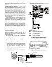
ASTP Protection Trip
— All non-digital Copeland compres-
sors are equipped with an advanced scroll temperature protec-
tion (ASTP). A label located above the terminal box identifies
models that contain this technology. See Fig. 25.
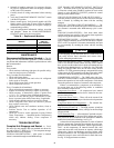
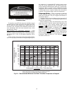
Advanced scroll temperature protection is a form of internal
discharge temperature protection that unloads the scroll com-
pressor when the internal temperature reaches approximately
300 F. At this temperature, an internal bi-metal disk valve
opens and causes the scroll elements to separate, which stops
compression. Suction and discharge pressures balance while
the motor continues to run. The longer the compressor runs un-
loaded, the longer it must cool before the bi-metal disk resets.
See Fig. 26 for approximate reset times.
MODULE
REPLACEMENT
PART NO.
(with Software)
Main Base Board (MBB) 30MP500346
Scrolling Marquee Display HK50AA031
Energy Management Module (EMM) 30GT515218
Navigator Display HK50AA033
CAUTION
If unit stoppage occurs more than once as a result of any of
the safety devices listed, determine and correct cause
before attempting another restart.