


51
been commanded OFF. This is done to facilitate a service tech-
nician forcing a relay to test a compressor.
In addition, if a compressor stuck failure occurs and the cur-
rent sensor board reports the compressor and the request off,
certain diagnostics will take place as follows:
1. If any of the compressors are diagnosed as stuck on and
the current sensor board is on and the request is off, the
control will command the condenser fans to maintain
normal head pressure.
2. The control will shut-off all other compressors.
The possible causes include welded contactor or frozen
compressor relay on the MBB.
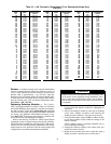
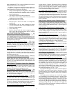
To check out alarms A051 to A053:
1. Place the unit in Service Test mode. All compressors
should be off.
2. Verify that there is not 24-v at the contactor coil. If there
is 24 v at the contactor, check relay on MBB and wiring.
3. Check for welded contactor.
4. Verify CSB wiring.
5. Return to Normal mode and observe compressor opera-
tion to verify that compressor current sensor is working
and condenser fans are energized.
A060 (Cooler Leaving Fluid Thermistor Failure)
— The
sensor reading is outside the range of –40 to 245 F (–40 to
118 C) then the alarm will occur. The cause of the alarm is usu-
ally a faulty thermistor, a shorted or open thermistor caused by
a wiring error, or a loose connection. Failure of this thermistor
will shut down the entire unit.
A061 (Cooler Entering Thermistor Failure)
— If the sensor
reading is outside the range of –40 to 240 F (–40 to116 C) then
the alarm will occur. The cause of the alarm is usually a faulty
thermistor, a shorted or open thermistor caused by a wiring er-
ror, or a loose connection. Failure of this thermistor will shut
down the entire unit.
T062 (Condenser Leaving Fluid Thermistor Failure)
— The
sensor reading is outside the range of –40 to 245 F (–40 to
118 C) then the alert will occur. The cause of the alert is usually
a faulty thermistor, a shorted or open thermistor caused by a
wiring error, or a loose connection. Failure of this thermistor
will send out an alert only.
T063 (Condenser Entering Thermistor Failure)
— If the sen-
sor reading is outside the range of –40 to 240 F (–40 to116 C)
then the alert will occur. The cause of the alert is usually a
faulty thermistor, a shorted or open thermistor caused by a wir-
ing error, or a loose connection.Failure of this thermistor will
send out an alert only.
T068 (Circuit A Compressor Return Gas Temperature
Thermistor Failure) — This alert occurs if the RGT is config-
ured and the compressor return gas temperature sensor is out-
side the range of –40 to 240 F (–40 to 116 C). Failure of this
thermistor will shut down the appropriate circuit.
T073 (Outside Air Temperature Thermistor Failure)
— This
alert occurs when the outside air temperature sensor is outside
the range of –40 to 240 F (–40 to 116 C). Failure of this therm-
istor will disable any elements of the control which requires its
use. The OAT must be configured.
T074 (Space Temperature Thermistor Failure)
— This alert
occurs when the space temperature sensor is outside the range
of –40 to 245 F (–40 to 118 C). Failure of this thermistor will
disable any elements of the control which requires its use. The
cause of the alert is usually a faulty thermistor in the T55, or
T58 device, a shorted or open thermistor caused by a wiring er-
ror, or a loose connection. The SPT must be configured.
A077 (Circuit Saturated Suction Temperature Exceeds
Cooler Leaving Water Temperature) — This alarm occurs
when the saturated suction temperature (SST) is greater than
leaving water for 5 minutes. This alarm will occur if either the
suction pressure transducer reading, which is used to calculate
SST, or cooler leaving water is incorrect. Potential causes for
this alarm are loose wiring connection, sensor not located in
well or bad Schrader fitting. Reset is manual.
T079 (Dual Chiller Thermistor Failure)
— This alert occurs
when the dual chiller temperature sensor is outside its range of
–40 to 240 F. Failure of this thermistor will disable Dual Chill-
er operation and return to stand-alone operation. The unit must
be configured for Dual Chiller operation for this alert to occur.
The cause of the alert is usually a faulty thermistor, a shorted or
open thermistor caused by a wiring error, or a loose connection.
Reset is automatic.
A090 (Circuit A Discharge Pressure Transducer Failure)
—
This alarm occurs when the pressure is outside the range of 0.0
to 667.0 psig. A circuit cannot run when this alarm is active.
Use the scrolling marquee to reset the alarm. The cause of the
alarm is usually a faulty transducer, faulty 5-v power supply, or
a loose connection.
A092 (Circuit A Suction Pressure Transducer Failure)
—
This alarm occurs when the pressure is outside the range of 0.0
to 420.0 psig. A circuit cannot run when this alarm is active.
Use the scrolling marquee to reset the alarm. The cause of the
alarm is usually a faulty transducer, faulty 5-v power supply, or
a loose connection.
T094 (Discharge Gas Thermistor Failure)
— This alert oc-
curs for units which have the digital compressor installed on
circuit A. If discharge gas temperature is open or shorted, the
circuit will be shut off. The alert will reset itself when discharge
temperature is less than 250 F (121.1 C). The cause of the alert
is usually low refrigerant charge or a faulty thermistor.
A110 (Circuit A Loss of Charge)
— This alarm occurs when
the compressor is OFF and the discharge pressure is less than
26 psig.
A112 (Circuit A High Saturated Suction Temperature)
—
Alarm code 112 occurs when compressors in a circuit have
been running for at least 5 minutes and the circuit saturated
suction temperature is greater than 70 F (21.1 C). The high sat-
urated suction alarm is generated and the circuit is shut down.
A114 (Circuit A Low Superheat)
— Alarm code 114 occurs
when the superheat of a circuit is less than 5 F (2.8 C) for 5
continuous minutes. The low superheat alarm is generated and
the circuit is shut down. The RGT sensor must be installed.
A122 (Circuit A, High Pressure Switch Failure)
— The
high pressure switch is wired in series with the compressor
contactor coils of each compressor on the circuit to disable
compressor operation immediately upon a high discharge pres-
sure condition. The normally closed contacts in the switches
are calibrated to open at 650 ± 10 psig which corresponds to a
saturated condensing temperature of 155.6 ± 1.3 F. The pres-
sure switches will automatically reset when the discharge pres-
sure is reduced to 500 ± 15 psig which corresponds to a saturat-
ed condensing temperature of 134.1 ± 2.4 F.
The output of the high pressure switch is wired to inputs on
the MBB to provide the control with an indication of a high
pressure switch trip. This alert could occur when compressors
are off if the wiring to the switch is broken or the switch has
failed open.
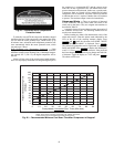
If the high pressure switch trips on a circuit with compres-
sors commanded on, the discharge pressure is recorded. If the
recorded discharge pressure is between 630 to 660 psig (satu-
rated condensing temperature between 153.0 and 156.9 F), and
is also less than the value recorded on any previous high pres-
sure switch trip, the upper horizontal portion of the compressor
operating envelope (see Fig. 12) is lowered 0.4 F (3 psig). The
control will not allow the compressor operating envelope to be
lowered below 153.0 F (630 psig).