


13
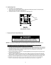
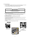
Figure 3
-
14
Electrical Connections
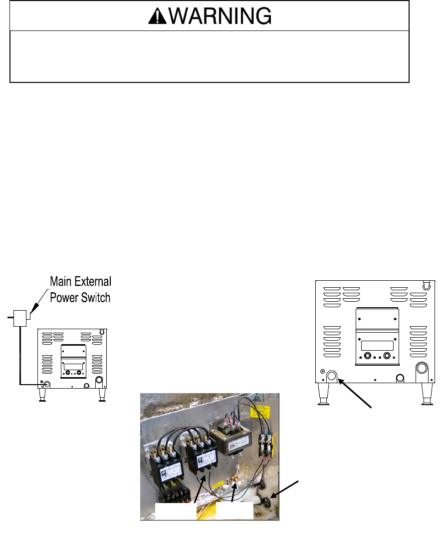
K. Electric Power Supply
• The electric supply must match all electrical and wiring requirements specified on the rating plate.
• NOTE: This appliance is NOT Ground Fault Interrupter (GFI or GFCI) compatible.
• The Electrical Diagram is located on the back of the control-side cover.
The connection must be made as follows:
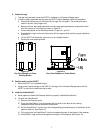
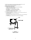
1. Install a main disconnect switch and a separate fuse or breaker for this appliance as shown in
Figure 3-12. The fused disconnect switch is called the “Main External Power Switch.”
2. Do not use a GFI (GFCI) circuit. This appliance is not GFI compatible.
3. Do NOT use a power cord.
4. Make the electrical connection using flexible conduit, per local code.
5. There should be a sufficient length of flexible conduit between the steamer and the wall so the
appliance can be moved for service.
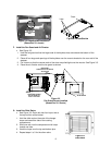
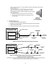
6. Mechanically secure the flexible conduit to the electrical access hole found at the rear of the
appliance. See Figure 3-13.
7. Refer to the wiring diagrams and Figure 3-14. Connect the wires to the terminal block and ground
connector.
8. The appliance must be electrically grounded by the installer.
Figure 3
-
12
Electrical Layout
GROUND
LUG
TERMINAL
BLOCK
WIRING
INLET
Figure 3
-
1
3
Electrical Connection Inlet
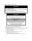
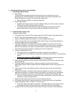
This appliance is not GFI (GFCI) compatible.
Do not use a GFI (GFCI) circuit.
Using a GFI (GFCI) circuit can result in injury, equipment damage, and property damage.
ELECTRICAL
INLET