


Chapter 14 Removal and replacement of parts
Page 14.1
14. Removal and replacement of parts
Warning:
• Electricity is dangerous and can kill. Disconnect the power supply before making any
connections or dis-assembling the 7951.
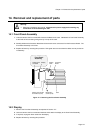
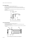
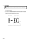
14.1 Front Panel Assembly
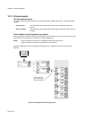
1. Undo and remove the four screws which secure the Bezel to the case. Withdraw the Front Panel Assembly
to the limits of the connecting wiring then lay it on top of the case.
2. Partially withdraw the Processor Board then disconnect the two connectors from the Processor Board. The
Front Panel Assembly is now free.
3. Replace all items by reversing this procedure. Take great care to ensure that the cables are not pinched on
re-assembly.
Switch panel
and bezel
Display
Front Panel
Assembly
Display
cable
PL1
PL2
Display fixing screws
and washers
(
4off
)
Bezel fixing
screws
(
4off
)
Processor
Board
Case
Figure 14.1: Removing the Front Panel Assembly
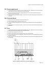
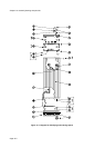
14.2 Display
1. Remove the Front Panel Assembly as explained in Section 14.1.
2. Undo and remove the four screws and washers which attach the display to the Front Panel Assembly.
3. If required, unplug the ribbon cable from the display.
4. Replace all items by reversing this procedure.