


Chapter 2 Getting started
Page 2.6
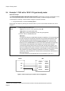
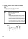
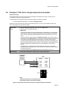
2.5 Example 2: 7951 with a 3096/3098 Gas Specific Gravity Meter
About this example
This example shows you how to connect a 3096/3098 to the 7951 and then use the “SG 1” wizard to configure
the system.
In this example, the “SG 1” wizard is used to configure a connection as follows:
x A single 3096/3098 is connected to Density Input 3.
Work through the example by following the instructions below. If you are not sure where the buttons are, refer to
Chapter 6.
Connect the
meter
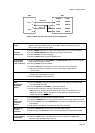
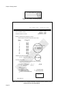
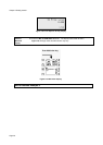
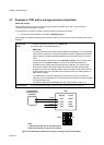
1. Wire the meter to the 7951, as in :
Figure 2.6 for a NON-HAZARDOUS (SAFE) AREA OR
Figure 2.7 for a HAZARDOUS AREA
2. Earth the 7951 to a suitable earth point.
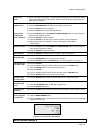
EMC Notes:
To meet the EC Directive for EMC (Electromagnetic Compatibility), it is recommended
that the Flow Computer be connected to transducers using a suitable instrumentation
cable containing individually shielded twisted pairs and an overall screen to cover all
cores.
The instrumentation cables should have individual screen(s), foil or braid over each
twisted pair and an overall screen to cover all cores. Where permissible, and depending
on the earthing scheme employed at the installation, the overall screen should be
connected to the earthed metal work at both ends (360° bonding where possible). This
may have multiple protective earth connections to the pipe work or the building structure
and not connected to the individual screen(s) or Instrumentation or Zener barrier grounds.
The individual inner screen(s) should be connected at one end only, normally the
controller (e.g. Flow Computer) end. These should be connected to the Instrumentation or
Zener barrier ground.
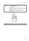
Use suitable cables that meet BS5308 multi-pair Instrumentation Types 1 or 2.
Signal +
Signal -
Sig
+
Neg
(24V) Power +
1
2
3
Klippon D-type
PL5/9
PL5/5
PL5/6
PL5/10
SK6/22
SK6/18
SK6/19
SK6/24
79513096/3098
(0V) Power -
4
40 ohms
Figure 2.6: Non-hazardous (Safe) area wiring for a 3096/3098