


Chapter 5 Installing the system
Page 5.4
5.7 Step 4: Fitting the 7951
Caution:
You must not fit the 7951 where it may be subjected to extreme conditions or be liable to damage.
For further information about the environmental conditions within which it can operate, see Appendix C.
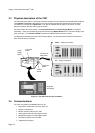
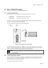
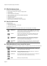
1. Firstly, referring to Figure 5.2, cut out an aperture in the front panel for each instrument which is to be
mounted on it.
Aperture for the
instrument
Aperture for the
instrument
Aperture for the
instrument
29±1mm
17±1mm
14.5mm
17.5mm
192±1mm
96±1mm
Aperture for the
instrument
Figure 5.2: Minimum dimensions for a panel with apertures to fit four 7951’s
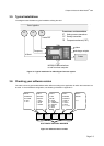
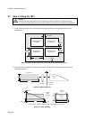
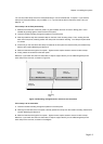
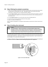
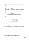
2. Each instrument is mounted in a clamp which is fixed to the rear of the front panel, as shown in the two
diagrams that follow.
Mounting
Clamp
The 7951 unit
Location
Moulding
278.7mm
101mm
Panel with
aperture
3mm
Figure 5.3: Before assembly
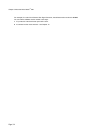
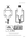
256mm
12.5mm
7.2mm
10mm
3mm
Captive
Clamp
Screws (2)
Rear Panel
of 7951
Mounting
Clamp
113mm
221mm
Note: Sufficient clearance is required for plugs and cables at the rear of the 7951
Figure 5.4: After assembly