


Chapter 5 Installing the system
Page 5.3
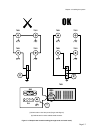
5.6 Step 3: Setting DIP-switches
Some types of connection may require DIP-switches to be set.
5.6.1 Analogue Input DP-switches
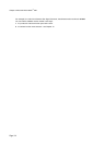
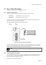
The 7951 has two blocks of DIP-switches on the Processor Board, as shown in Figure 5.1:
x SW1 switches
– select whether each input is 4-20 mA or PRT.
x SW2 switches
– not used in the current version of 7951.
The setting of each switch in the SW2 block must be the same as the corresponding pair of switches in the
SW1 block. The 7951 may not work correctly otherwise.
The 7951 is supplied with the DIP-switches in these default settings:
x Input 1 PRT
x Inputs 2-4: 4-20mA
Part of the 7951
Processor Board
1
2
3
A
B
C
4
D
SW2
SW1
PRT
4-20mA
Figure 5.1: DIP-switches on the Processor Board
If you want to change the Analog Input switch settings, you must also configure the inputs. This is explained in
chapter 11. After the configuration has been completed, the 7951 should be switched into the 'secure' mode to
prevent unauthorised or accidental tampering with the instrument's configuration.
Note:
x The 7951 is always shipped from the factory with the security lock on the front panel set to the
‘non-secure’ mode.
5.6.2 Turbine Voltage Selection switches
The Turbine Voltage Selection switch is a DIP switch on the PSU Board, which is accessible through removal of
parts (see Chapter 14). Choose between 8 volts dc or 16 volts dc for all flow meters powered by the 7951.
The 7951 is shipped with the switch set for 8 volts dc.
For flow meter connection details, see chapter 2.