


Appendix C Technical data for the 7951
Page C.13
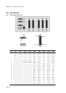
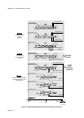
E E 0v +24V
DC Power
Protect Ground
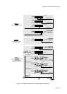
Group 1
Chassis and instrumentation
are earthed together
unless you cut the link
Group 2
No earthing is required
for Status Inputs
SK3
Link
PL2
Chassis
Earth
Earth
stud
Group 3
Connect external earths as
required.
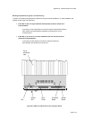
Pin 1
Pin 9
Protect Ground
SK2
Pin 1
Pin 9
Protect Ground
Common
SK1
Pin 1
Pin 9
Common
Common
PL2
Pin 10
Pin 1
Status Outputs Common
PL9
Pin 1
Pin 10
Analogue Power -
Density Power -
Pin 1
Pin 10
PL5
PL4
Turbine Power -
Pin 10
Pin 1
Internal Isolated Supply
PL6
Pin 10
Pin 1
Internal Isolated Supply
PL3
Pin 10
Pin 1
Opto-isolator common only
PL3
Pin 10
Pin 1
Pulse Outputs Common
SERIAL
PORT
PULSE
OUTPUTS
STATUS
OUTPUTS
STATUS
INPUTS
ANALOGUE
OUTPUTS
SERIAL
PORT
SERIAL
PORT
Figure C.1: Earthing arrangements for the 7951 (Klippon connectors)