21
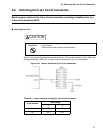
2.4 Connecting the External Probe
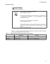
Notes:
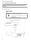
• To connect the external probe to the user system, check the signal name indicated on the
label on the external probe and connect it to the user system with a test clip.
• The connection of the test clip and signal line is not strong. Do not add stress by pulling on
the external probe.
• Firmly connect the connector that connects the external probe to the emulation pod.
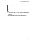
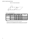
Table 2.4-1 External probe data
Color External probe data Color External probe data
Black CH0 (channel 0 input) Green CH5 (channel 5 input)
Brown CH1 (channel 1 input) Blue CH6 (channel 6 input)
Red CH2 (channel 2 input) Purple CH7 (channel 7 input)
Orange CH3 (channel 3 input Gray CK (external clock input)
Yellow CH4 (channel 4 input) Black GND (ground)


