


25
2.7 Emulator-specific Power Supply
2.7 Emulator-specific Power Supply
Set the jumper switch (S2) as follow by the function of the evaluation MCU.
1. Emulator-specific power supply switching
The setting of the emulator power supply switch depends on the power supply
function of the tool interface of each evaluation MCU.
■ Switching the Emulator Power Supply
Follow the precautions described below when setting of the emulator power supply switch.
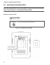
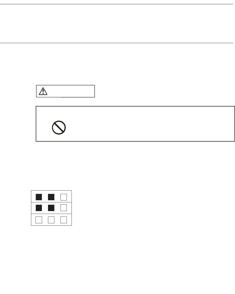
■ Jumper Switch (S2) Configuration
Set the emulator-specific power supply switch according to the function of the evaluation MCU
and target board.
For information on the emulator-specific power supply pin of an evaluation MCU, see the
hardware manual of each product.
Before setting the jumper switch for the power supply, turn off the
power.
Failure to do so may cause an electric shock.
CAUTION
Prohibition
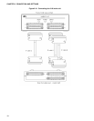
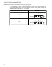
(1) UVCC1
(2) UVCC1
(3) UVCC1
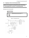
UVCC2 [Fixed] Jumper switch for the function extension
(A-B shorted)
1. Reserved [setting of (1) and (2)]
These jumper switches are reserved for the function extension.
These switches short-circuit on the A-B side.
2. Emulator-specific power supply switching [setting of (3)]
On the evaluation MCU, select the user system power supply (UVCC1) or the development tool power
supply (+5V) as the tool interface power supply to the development tool by setting the jumper switch for
switching the emulator-specific power supply.
If the evaluation MCU has a emulator-specific power supply pin, the development tool power supply (+5V)
must be connected as the tool interface.
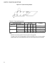
UVCC2 [Fixed] Jumper switch for the function extension
(A-B shorted)
+5V [Selected] Jumper switch for switching the emulator-specific
power supply
A B C
S2
*: UVCC1 (A-B shorted): MCU power supply
+5V (B-C shorted): Development tool power supply