Part # 1844063 (08/06)Page 8
ASSEMBLY INSTRUCTIONS Continued
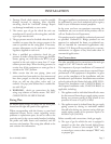
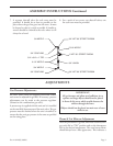
1. Slide the wooden frame out of the oven.
2. Before installing the hearth core plates or steel
hearth assembly, be sure that the bottom heat
deflectors are properly positioned with the treaded
side (bumps) in the up position.
3. If the oven is supplied with a steel hearth assembly,
place the hearth spacers (with the flat side in the
up position) on the extreme left and right sides of
the oven resting on the heat deflectors. Making sure
the hearth spacers are not disturbed, slide the steel
hearth assembly into the oven.
4. If oven is supplied with hearth core plates, slide the
plates into the oven.
GPD-48 is supplied with (2) two hearth core plates.
GPD-60 is supplied with (3) three hearth core plates.
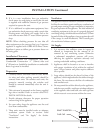
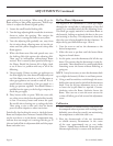
5. Installation instruction for Hearth.
a. Place a screwdriver, or a similar prying
device, between the core plate and hearth
frame support, (being careful not to chip
the core plate) then place two spacer clips
(PN G03086-1-9) between the core plate and
the hearth frame support. (See instructions
sheet – PN 1917401) 6” from front & 6” from
rear.
b. Place a screwdriver between the back of the
right core plate and hearth frame support. Pry
the core plate forward, away from the hearth
support and place a clip within the space
centered on each core plate.
c. Repeat step 2 for the left core plate
d. Repeat step 3 for the center core plate for 60”
unit.
Double Deck Assembly
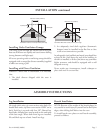
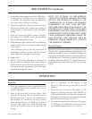
1 Secure legs to lower section
2. Remove stainless steel top trim strip from lower
unit if not already removed.
3. Tip upper unit backward. Remove vent patch at
lower rear if not if not already removed.
4. Place 1” x 4” x 65” (25mm x 100mm x 1650mm)
long piece of lumber across the rear top of oven to
prevent stacks from misarranging.
5. Raise the top oven section up and onto the lower
oven section.
6. Carefully remove piece of lumber ensuring lower
section vent collar inserts into upper section vent
hole.
Gas Connection
1. e appliance must be isolated from the gas supply
piping system by closing its manual shut-off valve
during any pressure testing of the gas supply piping
system at test pressure equal to or less that ½ psig.
(3.45 kpa.).
2. e appliance and its shut off valve must be
disconnected from the gas supply piping system
during any pressure testing of that system at test
pressures in excess of ½ psig. (3.45 kpa.).
NOTE: e ovens should not be installed on the same
line with space heaters, broilers or other equipment
with high intermittent demand.
3. When making gas connections, uses a pipe joint
compound that is resistant to the action of liquefied
petroleum gases.
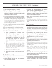
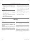
4. Each oven is supplied with two possible gas
connection locations. One is located on the right
side and the other is located on the right rear
corner.
5. e right side connection is plugged with a ¾
counter sunken plug. If this connection is used, you
must cap the rear connection.
6. e gas pressure regulator is part of the combination
valve and is adjusted to yield a pressure of 6.0” water
column for natural gas and 10” water column for
propane gas.


