


– 15 –
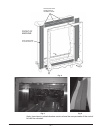
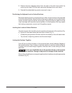
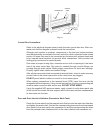
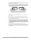
PERMAGUM
SADDLE
JOINTPERMAGUM
Fig. 13
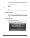
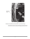
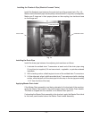
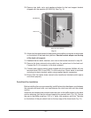
Control Box Connections
Refer to the electrical diagram stored inside the main control box door. After use,
make sure that the diagram is placed inside the control box.
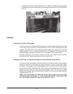
Although each section is prewired, components in the load and unload sections
must be electrically connected to the main control box that is attached to the unload
section. All wires that need to be connected are furnished with stripped leads and
have crimped barrel terminal for terminal block connections. Also provided are
locking plug connectors for control boards.
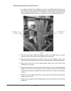
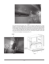
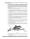
Run wires in proper routing clips, channels and so forth to openings in the lower
rearofthemaincontrolbox.Runwires(inconduit)throughconduitttings;run
cordage through strain reliefs. Make proper connections for wires and cordage.
Properlytightenstrainreliefsandconduitttings.
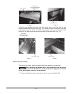
After all wires are routed and connected at terminal block, check to make sure any
unused holes in the lower rear portion of the control box are plugged.
DO NOT permit electric cables or conduit to touch steam pipes.
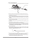
When making connections to the terminal block (8TB), insert the wire into the
designated terminal opening. Using a small screwdriver, pry the corresponding tab
down to make connection and secure wire. DO NOT STRIP WIRES.
Using the supplied NSF-approved sealer, apply a bead of caulk where each side
of the control box meets the tank support rails to allow any moisture condensation
to drain back into the tank.
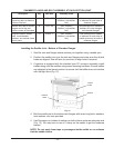
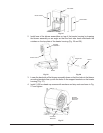
Door and Drain Interlock Switches (Prewash to Wash Tank)
Routethe4-wirecablefromtheprewashtankoatboxintothewashtankoatbox
and tighten the strain relief. Connect the corresponding two wires from the prewash
door switch to the door switch wire connector nut and the corresponding two wires
from the prewash drain interlock switch to the drain interlock wire connector nut.