


– 23 –
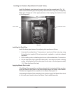
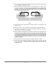
5. Repeat steps 2 thru 4 to install the second blower assembly.
6. Route both blower cables between the blower assemblies and the vertical
enclosure panel to the rear of the control box.
NOTE: Ensure that the cables are not routed on the side of the blowers where the
air intake chamber openings are located.
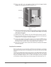
7. Connect blower motor wires labeled 10MTR -1, -2, & -3 and 11MTR -1, -2, &
-3, with the wire connectors already connected to the blower motor cables, to
the corresponding wires at the rear of the control box which are also labeled
10MTR -1, -2, & -3 and 11MTR -1, -2, & -3.
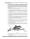
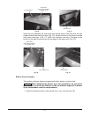
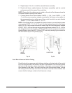
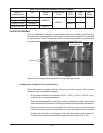
NOTE: If the blower dryer is equipped with electric heaters, connect electric heater
wires marked 7HTR-1, -2, -3, -4, -5 and -6 to the heating elements in the blower
dryer (Fig. 28). Also connect the electric heater high limit over temp wires marked
6TAS-C, -NC, & -NO and the over temp warning light wires marked 1PL-X1 & -X2 to
the designated terminals located on 6TAS high limit switch mounted to the electric
heater element cover plate (Fig. 29) and 1PL over temp warning light mounted on
the front blower dryer cover panel (Fig 29).
ELECTRIC
HEATER
ELEMENTS
1PL OVER TEMP
WARNING LIGHT
6TAS
HIGHT
LIMIT
Fig. 28 Fig. 29
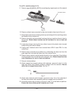
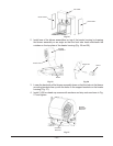
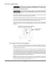
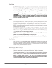
Dual Rinse Pressure Switch Tubing
Route the dual rinse pressure switch tubing, coiled up on the back side of the control
box, thru the grommet in the panel at the rear of the machine. Run the tubing down
the back of the chamber, across the bottom of the tanks, and connect to the air
trap mounted to the side of the dual rinse tank with the provided clamp. Secure
the tubing with the tie straps mounted to the studs on the rear of the chamber and
ensure that the tubing is routed so that there are no traps.