


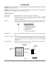

– 10 –
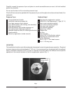
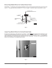
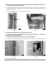
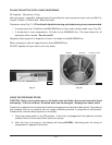
10. Mount the base of the outer exhaust manifold to the top of the condensation tank (Fig. 11) and
secure with the two flat head
1
/4-20 screws.
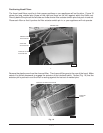
11. Install the inner exhaust manifold (Fig. 12) to the inside of the hood using the four
1
/4-20 hex head
screws and four wing nuts provided. Insert a gasket between each manifold and its mating
surface of the hood.
12. Slide the drip cup (Fig. 12) into the slots below the trough.
Fig. 11 Fig. 12
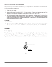
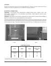
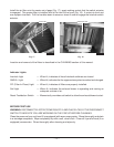
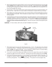
13. Remove the cover plate (Fig. 13) at the right rear of the fryer.
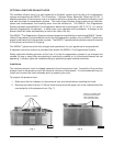
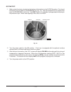
14. Locate the five-pin female receptacle at the right of the solenoid box (Fig. 14). Remove and
discard the jumper plug (if present).
15. Connect the five-pin male hood plug to the five-pin female receptacle.
Fig. 13
10. Mount the base of the outer exhaust manifold to the top of the condensation tank (Fig. 11) and
secure with the two flat head
1
/4-20 screws.
Fig. 11 Fig. 12
13. Remove the cover plate (Fig. 13) at the right rear of the fryer.
14. Locate the five-pin female receptacle at the right of the solenoid box (Fig. 14). Remove and
discard the jumper plug (if present).
15. Connect the five-pin male hood plug to the five-pin female receptacle.
16. Install the 1
1
/4" pipe plug (supplied) into the opening on the left side of the condensation tank.
Fig. 14
17. Apply power to the fryer.
PL-41460-1
OUTER
EXHAUST
MANIFOLD
CONDENSATION
TANK
PL-41461-1
DRIP CUP
INNER EXHAUST MANIFOLD
PL-41462-1
COVER PLATE
PL-41463-1
JUMPER PLUG