


– 4 –
Carefully unpack the pressure fryer and place in a work-accessible area as near to its final installed
position as possible.
Do not use the door to lift or move the pressure fryer.
Check off the accessories packed with the pressure fryer and the optional ventless exhaust hood (if so
equipped).
Pressure Fryer Optional Hood
Frying basket and handle
Hood and fire suppression system
Instruction manual and parts list
ANSULEX
®
Fire Suppressant, 1.5 gal. (5.7 L)
Four legs, pressure fryer cabinet Rear (outer) exhaust manifold
Four swivel casters (two locking, two standard) Front (inner) exhaust manifold
Drain pipe extension Drip cup, inner manifold
Solenoid wrench and flexible cleaning rod Two manifold gaskets
Two replacement diaphragm gaskets Spacer bar, drilled
Wooden doughnut stick (for clearing kettle drain) Grease filter
Crumb catcher Air filter
Warranty registration (inside manual) Charcoal filter
Tube of RTV108 adhesive sealant
Pipe plug for condensation tank
Mounting Hardware:
Four
1
/4-20 x 1" hex head screws
Four
1
/4-20 wing nuts
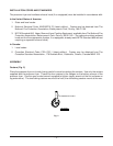
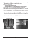
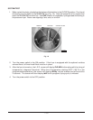
LOCATION
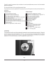
The installation location must allow adequate clearances for servicing and proper operation. Required
minimum clearance from side and back is 1" (2.5 cm)
. If your pressure fryer is equipped with the optional
hood, a minimum clearance of 30" (76 cm) is required on the left side of the exhaust hood to permit
operation of the manual actuator of the fire suppression system (Fig. 1).
Fig.1
PL-41452-1
MANUAL PULL FOR
FIRE SUPPRESION
SYSTEM