


~...L.....——
,., -s~
I
~
mFR@wiaEm&QwATEGM suPrkY
?>,Yourrange is designed to operateat a pressure
:~of4 inches ofwater columnon naturalgas or,if
F designedfor LPgas (propaneor buta~~e),10
~ inches
of water column. Make sure you are
~~~-utip~yingyour range
with the type ~fgas for
~vhichit is
designed.E, at anytimeinthe future,
you decide to u<ethis rangeon a differenttype
ofgas, conversionadjustmentsmust be made
by a service technicianor other quaMed
person before attemptingto operatethe range
on that gas.
For proper operation,the pressure ofnatiral gas
suppliedto the regulator must be between4 and
13inches ofwater column.For LPgas, the
pressure suppliedmust be between 10and 13
bches ofwater column.When checkingfor
proper operationofthe regulator,the inlet
pressure must beat least 1inch greater than the
operating (mmifold)pressure as givenabove.me
pressure regulator locatedat the inletofthe range
manifoldmust remain in the supplyke
regardless ofwhether naturalor LPgas is being
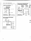
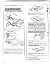
used, A flexiblemetil appliance.connectorused to
connect the range to the gas supplyline should
have an I.D. of l/2f1and be 5 feet in length
(shorter and longer lengths are acceptable)for
ease ofinstallation.
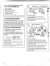
Shut off the main gas supplyvalvebefore
disconnecting the oldrange and leaveit off until
newhook-uphas been completed.Don’tforget to
relight the piloton other gas applianceswhen you
turn the gas back on.
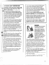
Because hard piping restricts movement ofthe
range, the use ofan AG.L-certified flexiblemetal
applianceconnector is recommended unless local
:odes require a hard-pipedconnection.Never use
ano~dconnector when installinga new range. If
:hehard piping method is used, you must
:arefullyalign the pipe;the range cannot be
noved after the connection is made.
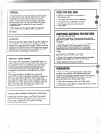
POprevent gas leaks, put pipejoint compound on,
~rwrap pipe thread tape with Teflon*around, all
~lale(external) pipe threads.
Teflon: Registered tradelnarlcofDuPont
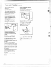
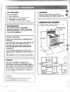
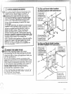
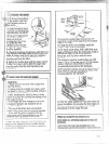
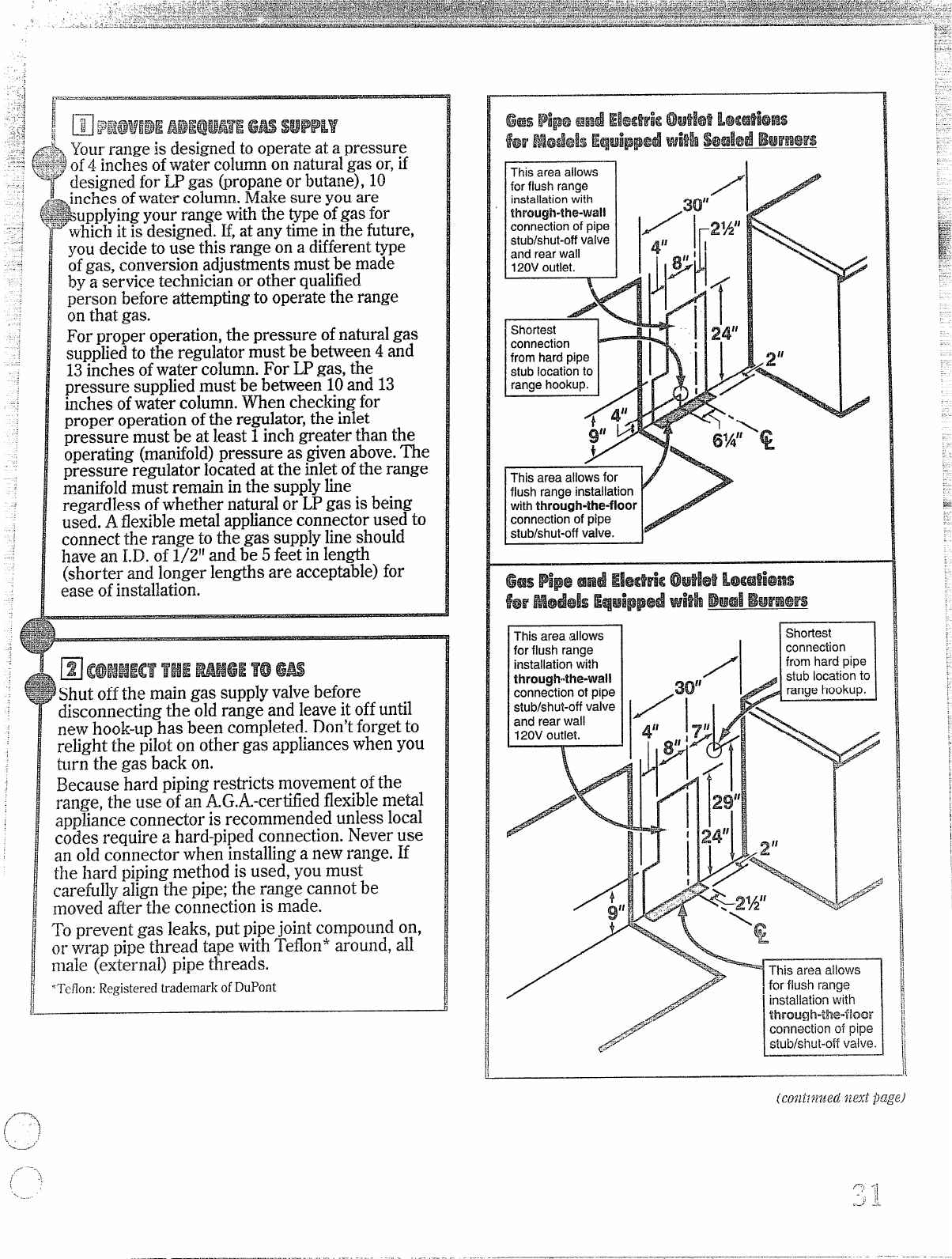
This area allows
I
~
for flush range
installation with
through-the-wa!!
connection of pipe
30”
z~g:~;:l
stublshut-off
valve 1/!1
and rear wall
II
H
120V outlet.
4“
~ 1#
,7:
/
This area allows
for flush range
1
installation with 1
tbrough”lhe”iloor
connection of pipe
stub/shut-oft
V~iV~.
.——
/“---,
,/’
(~
..+...-_r”f
,,...—-.
‘\
;
\
.