


12
CDVX Series Direct Vent Gas Fireplace
20012253
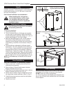
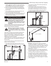
General Information Assembling Vent Pipes
Canadian Installations:
Venting system must be installed in accordance with the
current CSA-B149.1 installation code.
USA Installations:
The venting system must conform with local codes and/
or the current National Fuel Gas code ANSI Z223.1/
NFPA 54.
Only venting components manufactured by MHSC can
be used in Direct Vent systems.
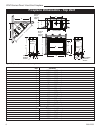
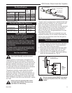
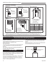
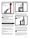
Flex Vent Pipes
Before joining the flex vent pipe to the unit, apply a
bead of high temperature sealant* (provided) to the 4”
pipe exiting the fireplace. Secure flex vent pipe in place
with a hose clamp (provided).
*Be sure the flex pipe overlaps at least 1” (25 mm) onto
the collars of the fireplace and termination. If the ter
-
mination has an internal bead, be sure to overlap and
secure 1” (25 mm) past the bead.
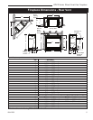
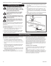
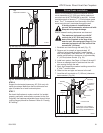
Fig. 11 Termination clearances.
* Be sure the vent is actually crushed before proceed-
ing. Apply a tug to be sure the vent will not slip off the
collars.
Repeat process with 7” flex vent pipe. The same proce-
dure must be performed on the vent side.
FP1471
flex vent
Hose Clamp
Apply High Tempera
-
ture Sealant
FP1471a
Fig. 12 Apply high temperature sealant to 4” and 7” pipes.
Outside Corner
Inside Corner
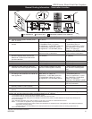
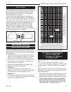
Termination Clearances
Termination clearances for buildings with combustible and noncombustible exteriors.
G =
Combustible
6" (152 mm)
Noncombustible
2" (51 mm)
F =
Combustible
6" (152 mm)
Noncombustible
2" (51 mm)
G
Balcony -
with no side wall
M =
Combustible &
Noncombustible
12" (305 mm)
M
Balcony -
with perpendicular side wall
M = 24" (610 mm)
P = 20” (508 mm)
M
F
Alcove Applications*
C
D
C
E
V
V
Combustible &
Noncombustible
V
V
V
E = Min. 6” (152 mm) for
non-vinyl sidewalls
Min. 12” (305 mm) for
vinyl sidewalls
O = 8’ (2.4 m) Min.
O
P
584-15
No.
of Caps D
Min.
C
Max.
1 3’ (914 mm) 2 x D
Actual
2 6’ (1.8 m) 1 x D
Actual
3 9’ (2.7 m) 2/3 x D
Actual
4 12’ (3.7 m) 1/2 x D
Actual
D
Min.
= # of Termination caps x 3
C
Max.
= (2 / # termination caps) x D
Actual
*NOTE: Termination in an alcove space (spaces open only on one side and with an overhang) is permitted with the dimensions
specified for vinyl or non-vinyl siding and soffits. 1. There must be a 3’ (914 mm) minimum between termination caps. 2. All
mechanical air intakes within 10’ (1 m) of a termination cap must be a minimum of 3’ (914 mm) below the termination cap. 3. All
gravity air intakes within 3’ (914 mm) of a termination cap must be a minimum of 1’ (305 mm) below the termination cap.