


9
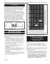
CDVX Series Direct Vent Gas Fireplace
20012253
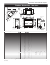
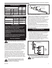
Gas Specifications
Max. Min.
Input Input
Model Fuel Gas Control BTU/h BTU/h
36CDVXRRN Nat Millivolt 21,000 14,700
36CDVXRRP* Prop Millivolt 21,000 15,750
36CDVXTRN Nat Millivolt 21,000 14,700
36CDVXTRP* Prop Millivolt 21,000 15,750
*Using conversion kit
Installation
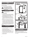
1. Carefully unwrap the remote wire that is attached to
the valve. There are two 1/2” (13 mm) knockouts,
one on each side of the outer casing.
2. Remove the knockout desired and insert the plastic
snap bushing on the remote wire in the 1/2” hole.
Feed the remote wire through the outer casing.
3. Attach the wire to an ON/OFF switch and install the
switch into the receptacle box. (Fig. 8)
Do not wire the remote ON/OFF wall switch
for the gas fireplace to the 120 volt power
supply.
Remote ON/OFF Switch
Always check for gas leaks with a mild
soap and water solution. Do not use an
open flame for leak testing.
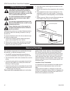
FP297A
INSTA VENT FREE
UVHB26 GAS SUPPLY
7/1/98
FP297A
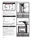
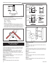
1/2” Gas Supply
1/2” NPT x 1/2” Flare Shut-
off Valve
3/8” Flex Line
(From Valve)
Fig. 7 Typical gas supply installation.
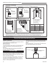
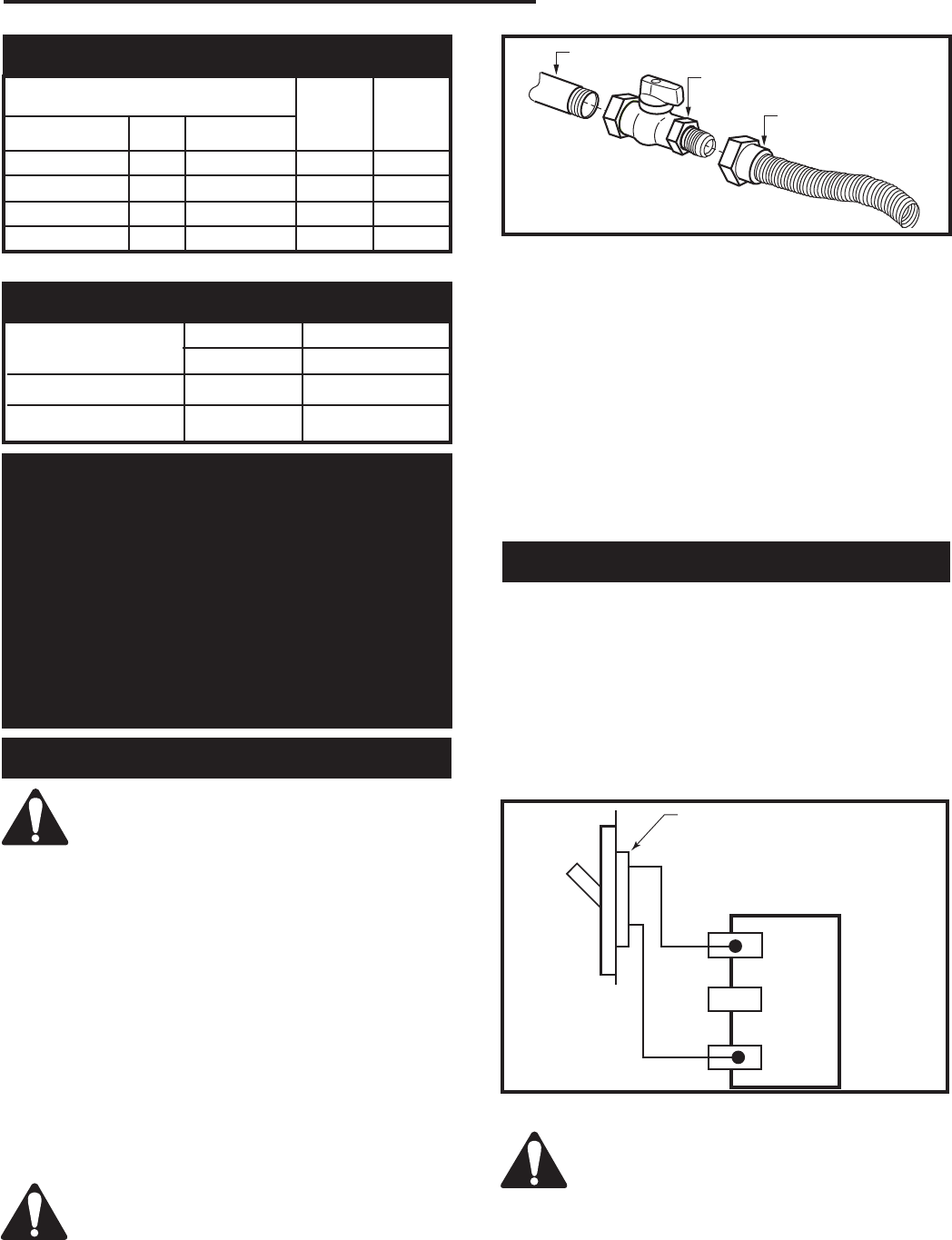
TP
TH
TP
TH
FP1224
Remote switch
11/02
Remote ON/OFF Switch
or Thermostat
or Remote Control
Gas
Control
Valve
FP1224
Fig. 8 Remote switch wiring diagram.
Gas Line Installation
When purging the gas lines, the front win-
dow frame assembly must be removed.
The gas pipeline can be brought in through the rear
of the appliance as well as the bottom. Knockouts are
provided on the bottom behind the valve to allow for the
gas pipe installation and testing of any gas connection.
It is most convenient to bring the gas line in from the
rear right side of the valve as this allows fan installation
or removal without disconnecting the gas line.
The gas line connection can be made with properly
tinned 3/8” copper tubing, 3/8” rigid pipe or an ap-
proved flex connector. Since some municipalities have
additional local codes, it is always best to consult your
local authority and the National Fuel Gas Code, ANSI
Z223.1/NFPA 54 in the USA or the CSA-B149.1 installa-
tion code.
The gas control is equipped with a captured screw type
pressure test point, therefore it is not necessary to pro-
vide a 1/8” test point up stream of the control.
When using copper or flex connector use only approved
fittings. Always provide a union when using black iron
pipe so the gas line can be easily disconnected for
burner or fan servicing. See gas specification for pres-
sure details and ratings.
The fireplace valve must not be subjected to any test
pressures exceeding 1/2 psi. Isolate or disconnect this
and any other gas appliance control from the gas line
when pressure testing.
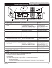
Inlet Minimum 5.5” w.c. 11.0” w.c.
Inlet Maximum 14.0” w.c. 14.0” w.c.
Manifold Pressure 3.5” w.c. 10.0” w.c.
Gas Inlet and Manifold Pressures
Natural LP (Propane)
High Elevations
Input ratings are shown in BTU per hour and are
certified without deration for elevations up to
4,500 feet (1,370 m) above sea level.
For elevations above 4,500 feet (1,370 m) in USA,
installations must be in accordance with the cur-
rent ANSI Z223.1/NFPA 54 and/or local codes hav-
ing jurisdiction.
In Canada, please consult provincial and/or local
authorities having jurisdiction for installations at
elevations above 4,500 feet (1,370 m).