


14
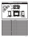
CDVX Series Direct Vent Gas Fireplace
20012253
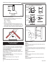
• Minimum clearances between vent pipe and com-
bustible materials are as follows:
Top - 1” (25 mm)
Sides - 1” (25 mm)
Bottom - 1” (25 mm)
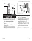
•
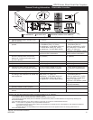
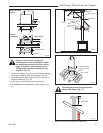
The maximum horizontal distance between the end
of the transition elbow in a corner application and the
outside face of the rear wall is 20” (508 mm). (Fig. 16)
• Only one 45° elbow is allowed in these installations.
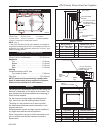
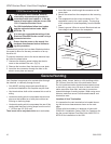
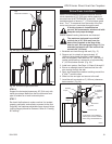
Top View
Straight Venting
Fig. 15 Rear vent applications.
20"
(508 mm)
Max.
FP1598
20” (508 mm)
Max.
FP1188
Fig. 16 Rear vent application, one 45° elbow.
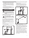
Rear Wall Installation
Twist Lock Pipe
STEP 1
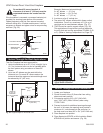
Locate vent opening on the wall. To locate hole center
consult with appropriate fireplace dimensions, Page 4.
Frame as shown below.
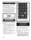
Combustible Walls
(Fig. 17): Cut a 9³⁄₈”H x 9³⁄₈” W
(240 x 240 mm) hole through the exterior wall and
frame as shown. For 7TCRVT1320 cut a 10
³⁄₈”H x 9³⁄₈”
W (264 x 240 mm) hole.
Noncombustible Walls
(Fig. 17): Hole opening must
be 7¹⁄₂” (190 mm) in diameter.
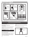
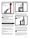
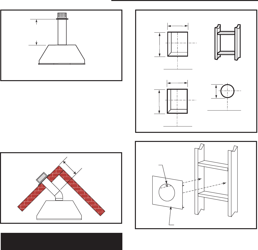
STEP 2
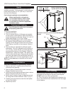
Install interior firestop as shown in Figure 18.
STEP 3
Remove telescoping collar from termination.
Firestop
FP1600
Fig. 18 Install firestop.
Bend Tab
STEP 4
Bend tab on outer casing up and insert collar onto fire-
place collars. (Fig. 18)
STEP 5
Twist the termination collar so it locks onto fireplace col-
lars. Run screw through tab to keep collar from turning.
(Fig. 19)
STEP 6
Slide fireplace into position.
STEP 7
From the outside of the house, slide the termination
onto the collars.
STEP 8
Secure the termination to the house with the four (4)
screws provided.
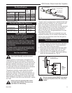
VO584-100
Vent Opening
2/99 djt
Vent Opening for Combustible Wall
9³⁄₈”
(240 mm)
9³⁄₈”
(240 mm)
Fireplace Hearth
Framing
Detail
Opening for Noncom-
bustible Wall
7¹⁄₂”
(190 mm)
VO584-100
Fig. 17 Locate vent opening on wall.
When using all
venting except
7TCRVT1320
9³⁄₈”
(240 mm)
10³⁄₈”
(264 mm)
When using
7TCRVT1320
venting Only