


26
CDVX Series Direct Vent Gas Fireplace
20012253
BG402a
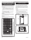
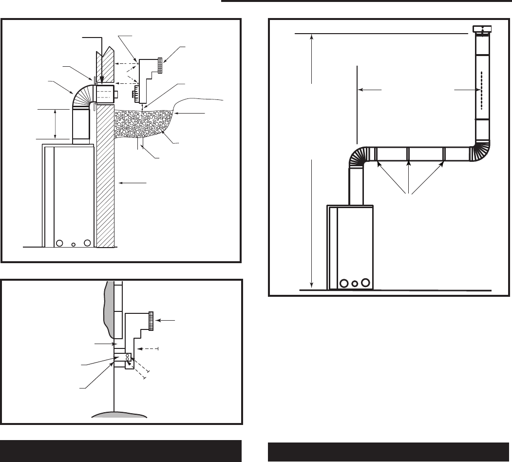
Top Vent
Below grade installation
1/26/00 djt
Firestop
7” Pipe
7TDVSNORK
(Snorkel)
4” (102mm)
Clearance
Min.
Window
Well
Gravel
Drain
BG402
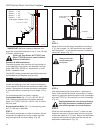
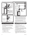
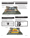
Fig. 53 Below grade installation.
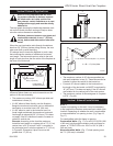
Zero Clearance Sleeve
(if required)
*A minimum of 24” (610mm) ver
-
tical pipe must be installed when
using the 7TDVSNORK Kit.
*The 22” (559mm) vertical rise
(center to center) of the snorkel
may be included for calculationof
max. horizontal run.
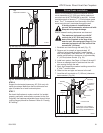
24” (610mm)
Minimum*
Screws
Foundation Wall
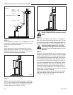
BG401
Snorkel
2/10/99 djt
Foundation Recess
Snorkel
Wall Screws
Recess Brackets
Watertight Seal
Around Pipe
Sheet Metal
Screws
BG401
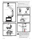
Fig. 54 Snorkel installation, recessed foundation.
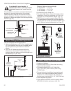
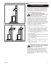
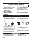
Vertical Through-the-Roof Applications
This Gas Fireplace has been approved for:
• Vertical installations up to 40’ (12 m) in height. Up
to a 10’ (3 m) horizontal vent run can be installed
within the vent system using a maximum of two 90°
elbows. (Fig. 55)
• Up to two 45° elbows may be used within the
horizontal run. For each 45° elbow used on the
horizontal level the maximum horizontal length must
be reduced by 18” (457 mm).
Example: Maximum horizontal length
0 x 45° elbows = 10’ (3 m)
1 x 45° elbows = 8¹⁄₂’ (2.6 m)
2 x 45° elbows = 7’ (2.1 m)
• A minimum of an 8’ (2.4 m) vertical rise.
Max. 10' (3m)
Max. Height
40' (12m)
Min. Height
7' (2.3m)
FP1244
through the roof
max/min dims
12/02
Pipe Straps Every
3’ (914mm)
FP1244
Fig. 55 Support straps for horizontal runs.
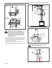
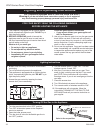
• Two sets of 45° elbows offsets within these vertical
installations. From 0 to a maximum of 8’ (2.m) of
vent pipe can be used between elbows. (Fig. 56)
• 7DVCS must be used to support offsets. (Fig. 58)
This application will require that you first determine
the roof pitch and use the appropriate starter kit.
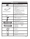
(Refer to Venting Components List)
• The minimum height of the vent above the highest
point of penetration through the roof is 2’ (610 mm).
(Fig. 60)
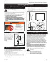
Vertical Through-the-Roof Installation
1. Locate your fireplace.
2. Plumb to center of the (4” (102 mm) flue collar from
ceiling above and mark position.
3. Cut opening equal to 9
³⁄₈” x 9³⁄₈” (240 x 240
mm).10³⁄₈” x 9³⁄₈” (264 x 240 mm) when using
7TCRVT1320.
4.
Proceed to plumb for additional openings through the
roof. In all cases, the opening must provide a minimum
of 1” (25 mm) clearance to the vent pipe, i.e., the hole
must be at least 9³⁄₈” x 9³⁄₈” (240 x 240 mm).
5. Place fireplace into position.
6. Place firestop(s) #7DVFS or Attic Insulation Shield
#7DVAIS into position and secure. (Fig. 57)
7. Install roof support (Fig. 58) and roof flashing making
sure upper flange of flashing is below the shingles.
(Fig. 59)