


24
CDVX Series Direct Vent Gas Fireplace
20012253
1
2
3
4
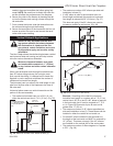
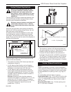
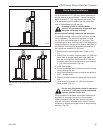
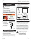
Example:
Elbow 1 = 90°
Elbow 2 = 45°
Elbow 3 = 45°
Elbow 4 = 90°
Total angular variation = 270°
1 + 2 + 3 + 4 = 270°
FP1239
Fig. 48 Maximum number of elbow degrees.
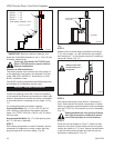
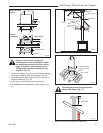
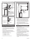
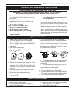
STEP 2
Place fireplace into position. (Fig. 49) Measure the verti
-
cal height (X) required from the base of the flue collars
to the center of the wall opening.
STEP 3
Attach appropriate venting component(s) to the fire
-
place with three (3) screws. (Fig. 50) Follow with the
installation of the inner and outer elbow. Again secure
joints with three (3) sheet metal screws.
X
FP1240
Fig. 49 Vertical height requirement.
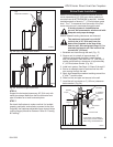
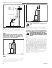
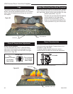
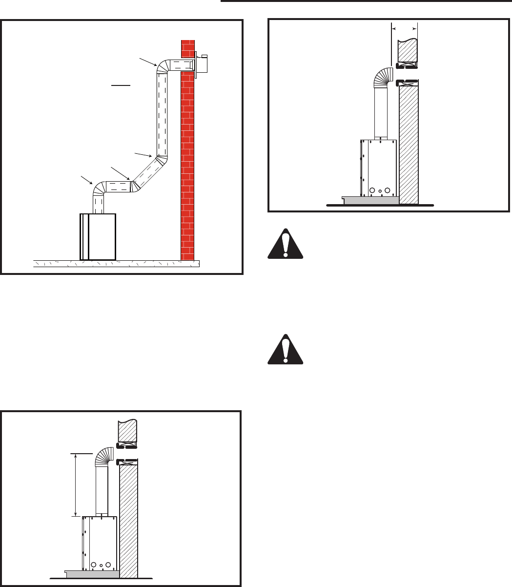
STEP 4
Measure the horizontal length requirement including
a 2” (51 mm) overlap, ie from the elbow to the outside
wall face plus 2” (51 mm) (or the distance required if
installing a second 90° elbow). (Fig. 50)
Always install horizontal venting on a level
plane.
STEP 5
Use appropriate length of pipe sections - telescopic or
fixed - and install the horizontal vent sections. The sec-
tions which go through the wall are packaged with the
starter kit, and can be cut to suit if necessary. (Fig. 48)
Sealing the gaps between the vent pipe
and firestop with high temperature sealant
will restrict cold air being drawn in around
fireplace.
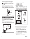
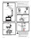
STEP 6
Guide the vent terminations 4” and 7” collars into their
respective vent pipes. Double check that the vent pipes
overlap the collars by 2” (51 mm). Secure the termina-
tion to the wall with screws provided and caulk around
the wall plate to weatherproof. (Fig. 52) As an alterna-
tive to screwing the termination directly to the wall you
may also use expanding plugs or an approved exterior
construction adhesive. You may also attach the termi-
nation with screws through the inner body into the 4”
(102 mm) vent pipe however for this method you must
extend the 4” (102 mm) pipe approximately 6” (152 mm)
beyond the outer face of the wall.
Support horizontal pipes every 3’ (914 mm) with metal
pipe straps. Make sure the horizontal vent pipe is in-
stalled on a level horizontal plane.
X
FP1241
Fig. 50 Horizontal length requirement.