


23
CDVX Series Direct Vent Gas Fireplace
20012253
Since it is very important that the vent-
ing system maintain its balance between
the combustion air intake and the flue
gas exhaust, certain limitations as to vent
configurations apply and must be strictly
adhered to.
The vent graph showing the relationship between verti-
cal and horizontal side wall venting will help to deter-
mine the various dimensions allowable.
Minimum clearance between vent pipes and
combustible materials is one 1” (25 mm)
on top, bottom and sides unless otherwise
noted.
When the vent termination exits through foundations
less than 20” (508 mm) below siding outcrop, the vent
pipe must flush up with the siding.
It is always best to locate the fireplace in such a way
that minimizes the number of offsets and horizontal
vent length. The horizontal vent run refert to the total
length of vent pipe from the flue collar of the fireplace to
the face of the outer wall.
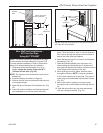
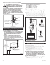
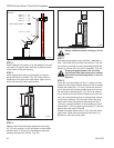
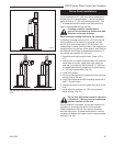
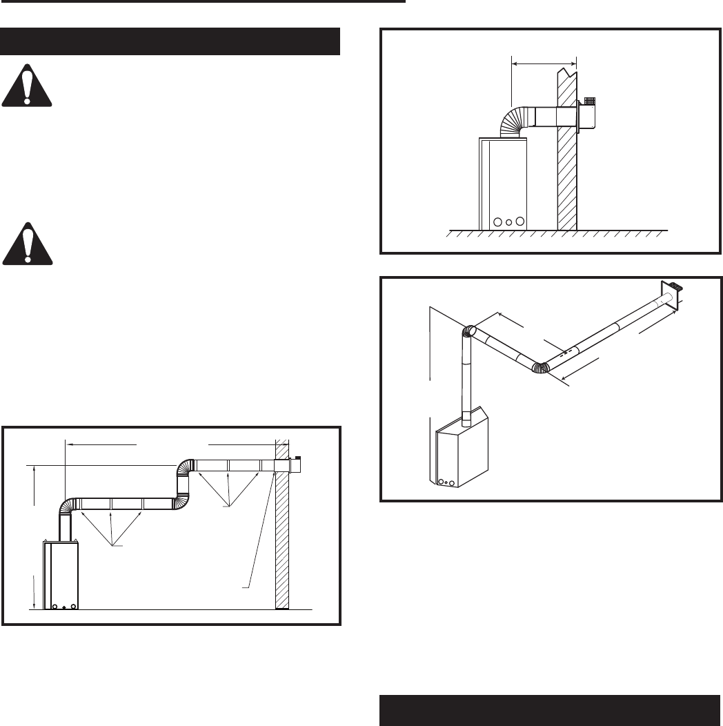
Vertical Sidewall Applications
FP1012
Top vent max run
1/25/00 djt
20' (6m)
7.5' (2.3m)
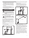
Pipe Straps
Every 3’ (914mm)
Firestop/Zero
Clearance Sleeve
Pipe
Straps Every
3’ (914mm)
FP1012
Fig. 45 Support straps for horizontal runs.
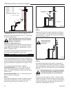
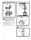
Horizontal plane means no vertical rise exists on this
portion of the vent assembly.
• The maximum number of 90° elbows per side wall
installations is three (3).
• If a 90° elbow is fitted directly onto the fireplace
flange the maximum horizontal vent run before the
termination or a vertical rise is 36” (914 mm).
• If a 90° elbow is used in the horizontal vent run
(level height maintained) the maximum horizontal
vent length is reduced by 36” (914 mm). This does
not apply if the 90° elbows are used to increase or
redirect a vertical rise.
Example: According to the chart the maximum
horizontal vent length in a system with a 7.5’ (2.3 m)
vertical rise is 20’ (6 m) and if a 90° is required in
the horizontal vent it must be reduced to 17’ (5.2 m).
In Figure 46, Dimension A plus B must not be
greater than 17’ (5.2 m).
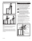
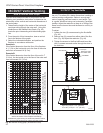
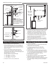
• The maximum number of 45° elbows permitted per
side wall installation is two (2). These elbows can be
installed in either the vertical or horizontal run.
• For each 45° elbow installed in the horizontal run,
the length of the horizontal run MUST be reduced by
18” (457 mm). This does not apply if the 45° elbows
are installed on the vertical part of the vent system.
• The maximum number of elbow degrees in a system
is 270°. (Fig. 48)
3'
(914mm)
FP1237
horizontal plane
12/02
FP1237
Fig. 46 Maximum horizontal vent run.
7.5'
(2.3m)
A
B
A + B = 17' (5.2m) Max.
1 x 90° elbow in horizontal plane = 3’ (914mm)
FP1238
Fig. 47 Maximum vent run with elbows.
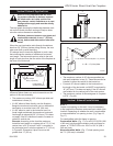
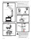
STEP 1
Locate vent opening on the wall. It may be necessary
to first position the fireplace and measure to obtain hole
location. Depending on whether the wall is combustible
or noncombustible, cut opening to size. (Fig. Page 13,
Fig. 17)
For combustible walls first frame in opening.
Combustible Walls:
(Fig. 17) Cut a 9³⁄₈”H x 9³⁄₈”W (240
x 240 mm) hole through the exterior wall and frame as
shown. or 7TCRVT1320 cut a 10³⁄₈”H x 9³⁄₈” W (264 x
240 mm) hole.
Noncombustible Walls:
(Fig. 17) Hole opening must
be 7¹⁄₂” (190 mm) in diameter.
Vertical Sidewall Installations