


33
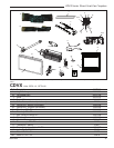
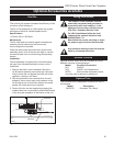
CDVX Series Direct Vent Gas Fireplace
20012253
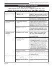
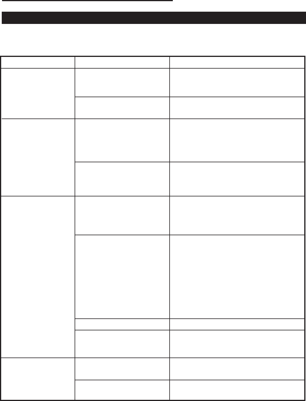
WARNING: BEFORE DOING ANY GAS CONTROL SERVICE WORK, REMOVE GLASS FRONT.
SYMPTOM POSSIBLE CAUSES CORRECTIVE ACTION
1. Spark ignitor will not light A. Defective or misaligned Using a match, light pilot. If pilot lights, turn off
electrode at pilot. pilot and push the red button again. If pilot will not
light - check gap at electrode and pilot-should be
1/8” to have a strong spark.
B. Defective ignitor (Push Button) Push Piezo Ignitor Button. Check for spark at
electrode and pilot. If no spark to pilot, and elec
trode wire is properly connected, replace ignitor.
2. Pilot will not stay lit after A. Defective pilot generator Check pilot flame. Must impinge on thermo
carefully following lighting (thermocouple), remote wall couple/thermopile. Note: this pilot burner assem
instructions. switch. bly utilizes both-a thermocouple and a thermopile.
The thermocouple operates the main valve
operation (On and Off). Clean and or adjust pilot for
maximum flame impingement on thermopile and
thermocouple.
B. Defective automatic valve Turn valve knob to “Pilot”. Maintain flow to pilot;
milivolt meter should read greater than 10 mV. If
the reading is okay and the pilot does not stay on,
replace the gas valve. Note: An interrupter block
(not supplied) must be used to conduct this test.
3. Pilot burning, no gas to A. Wall switch or wires defective Check wall switch and wires for proper connec
main burner tions. Jumper wire accross terminals at wall
switch, if burner comes on, replace defective wall
switch. If okay, jumper wires across wall switch
wires at valve, if burner comes on, wires are faulty
or connections are bad.
B. Thermopile may not be 1. Be sure wire connections from thermopile at
generating sufficient gas valve terminals are tight and thermopile is fully
millivoltage. inserted into pilot bracket.
2. One of the wall switch wires may be grounded.
Remove wall switch wires from valve terminals if
pilot now stays lit, trace wall switch wiring for
ground. May be grounded to fireplace or gas
supply.
3. Check thermopile with millivolt meter. Take
reading at thermopile terminals of gas valve.
Should read 250-300 millivolts (minimum 150)
while holding valve knob depressed in pilot
position and wall switch “Off”. Replace faulty
thermopile if reading is below specified minimum.
C. Plugged burner orifice. Check burner orifices for debris and remove.
D. Defective automatic valve Turn valve knob to “On”, place wall switch to “On”
operator. millivolt meter should read greater than 100 mV. If
the reading is okay and the burner does not come
on, replace the gas valve.
4. Frequent pilot outage A. Pilot flame may be too low Clean and/or adjust pilot flame for maximum flame
problem. or blowing (high) causing the impingement on thermopile and thermocouple.
pilot safety to drop out.
B. Possible blockage of the vent Check the vent terminal for blockage (recycling the
terminal. flue gases)
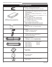
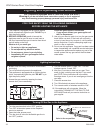
Troubleshooting the Gas Control System
NOTE: Before trouble shooting the gas control system, be sure external gas shut off is in the “On” position.
SIT NOVA 820 MILLIVOLT VALVE