16
CDVX Series Direct Vent Gas Fireplace
20012253
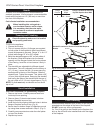
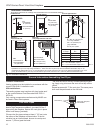
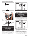
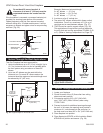
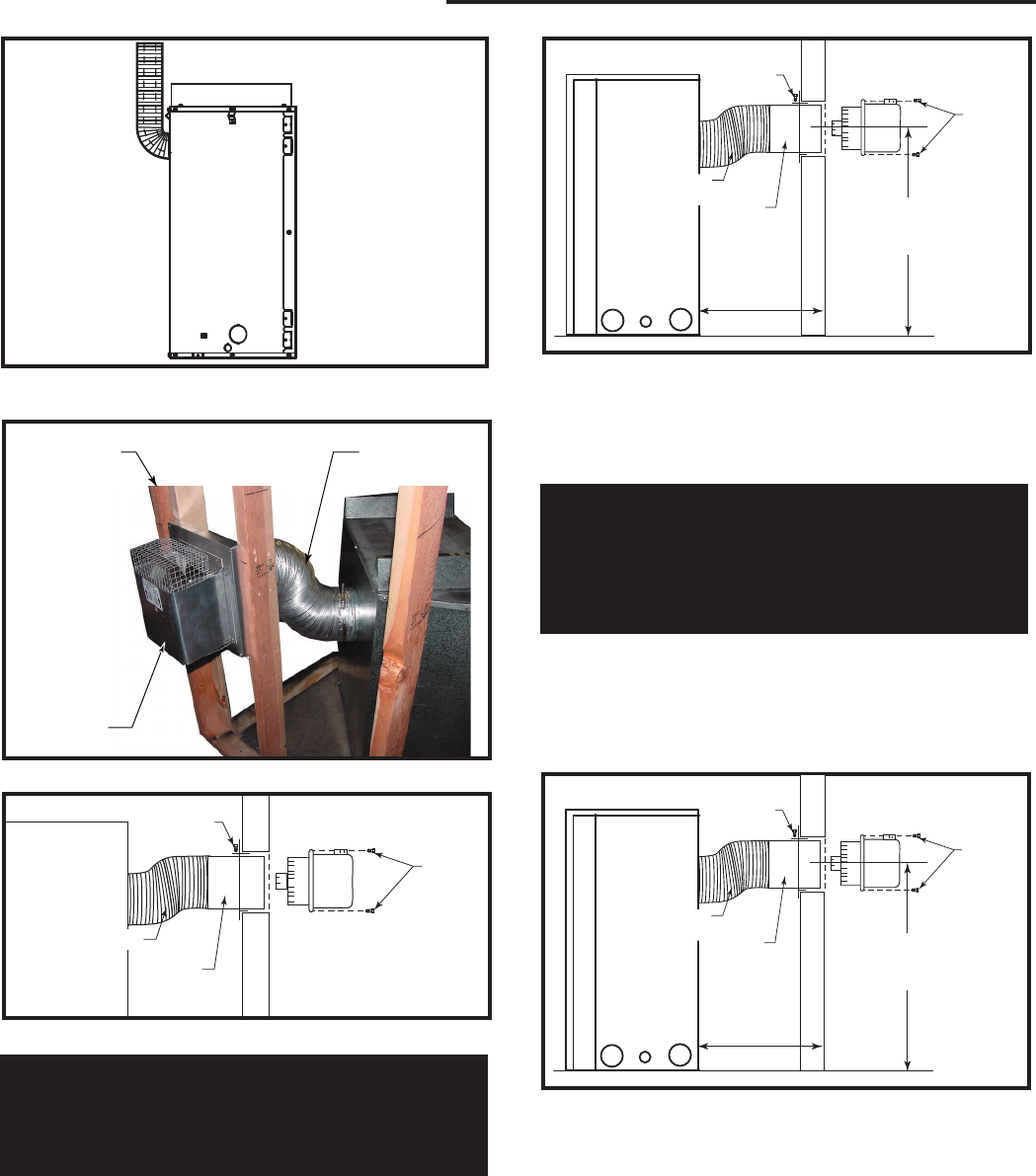
Fig. 21 Bend flex pipe up 90° as close to fireplace as pos-
sible.
FP1604
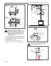
Do Not Exceed
45° Bend
Corner
Framing
Termination
FP1606
Fig. 22 Rear view of corner installation.
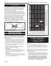
Screw
Collar
Screws
FP1605
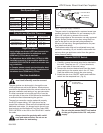
Fig. 23 Secure collar in place, slide termination into collar.
Flex Vent
Rear Wall Vent Application
* Exterior Outside Wall
13” to 20” (330 - 508 mm)
From Rear of Unit * Using Flex Venting Kit
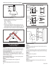
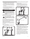
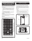
1. Determine the location of the termination. (Fig. 24)
IMPORTANT: Vent must have a 2¹⁄₂” (64 mm) rise
for this application.
2. Locate the hole 24¹⁄₂” (622 mm) off the floor. This
is the center line of the termination. Refer to “Rear
Wall Installation Twist Lock Pipe” section.
Screw
Screws
Flex Vent
Collar
FP1605a
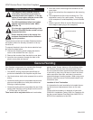
Fig. 24 The centerline of the termination must be 24¹⁄₂”
(622 mm) off the floor.
24¹⁄₂”
(622 mm)
13” - 20”
(330 - 508 mm)
3. Proceed with Step 3 of “Rear Wall Vent Application
*Exterior Outside Wall 20” to 32” (508-813 mm) from
Rear of Unit” section (below).
Rear Wall Vent Application
* Exterior Outside Wall
20” - 32” (508 - 813 mm)
From Rear of Unit * Using Flex Vent Kit
7TCD45KT
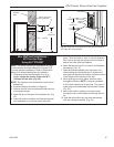
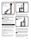
1. Determine where the termination is to be installed.
(Fig. 25)
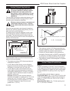
2. Locate the hole 27¹⁄₄” (692 mm) off the floor. This
is the center line of the termination. Refer to “Rear
Wall Installation Twist Lock Pipe” section.
Screw
Screws
Flex Vent
Collar
FP1605a
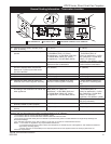
Fig. 25 The centerline of the termination must be 27¹⁄₄”
(692 mm) off the floor.
27¹⁄₄”
(692 mm)
20” - 32”
(508 - 813 mm)
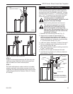
3. Mount the flex pipe assembly to the fireplace collars
and twist the collar that the flex pipe is attached to
onto the fireplace.
4. Once the collar is twisted onto the fireplace collar,
secure with a screw through the tab. (Fig. 19)
5.
While sliding the fireplace into position, lift up the end
of the flex pipe and slip it through the firestop. *Be
careful not to extend the flex too much. The flex pipe


