


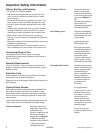
Component Testing Procedures
!
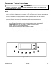
WARNING
To avoid risk of electrical shock, personal injury or death; disconnect power and gas to oven before servicing,
unless testing requires power and/or gas.
14 16023522
©2004 Maytag Services
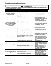
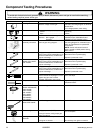
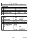
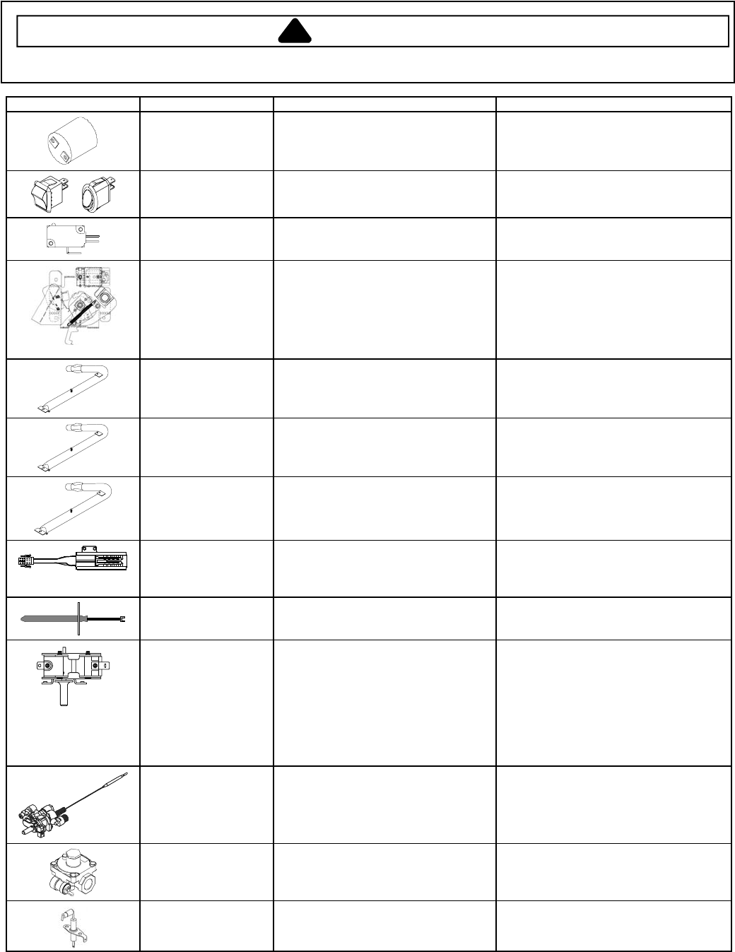
Illustration Component Test Procedure Results
Oven light socket Test continuity of receptacle terminals ...
Measure voltage at oven light.................
Indicates continuity with bulb inserted.
120 VAC, see wiring diagram for terminal
identification.
If no voltage present, check wiring.
Rocker switch Measure continuity of switch positions:
Closed.................................................
Open...................................................
Continuity
Infinite
COM
NO
NC
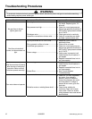
Door lock switch Switch connection in following
positions: Not engaged ........................
Engaged ..............................
Normally Open
COM-NO=Open, COM-NC=Closed
COM-NO=Closed, COM-NC=Open
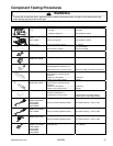
Manual Latch
assembly with switch
Disconnect wires and test for
continuity per wiring diagram..................
See wiring diagram for schematic layout.
Refer to Parts Manual for replacement
components.
NOTE: Control will cancel function if
latch is moved to LOCK position during
Bake or Broil.
Bake burner Verify gas is supplied.
Verify proper orifice installed-Nat or LP..
Check for obstructions, contamination
in ports or damage .................................
Air shutter opening: .469" to .531".
Blue flame with no yellow tipping.
Replace if punctured or torn.
Bake burner
Models CPL1100AD*,
CGL1100AD*
Verify gas is supplied.
Verify proper orifice installed-Nat or LP..
Check for obstructions, contamination
in ports or damage .................................
Air shutter opening: .349" to .411".
Blue flame with no yellow tipping.
Replace if punctured or torn.
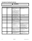
Broil burner Verify gas is supplied.
Verify proper orifice installed-Nat or LP..
Check for obstructions, contamination
in ports or damage .................................
Air shutter opening: .281" to .343".
Blue flame with no yellow tipping.
Replace if punctured or torn.
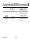
Ignitor Test for voltage at terminals...................
Test for amount of amperage in circuit ...
(Ignitor may glow, but not have
sufficient amperage to open valve).
120 VAC
3.2 to 3.6 Amps.
Temperature sensor Measure resistance................................
Approximately 1000 Ω at room
temperature 80
°F.
Gas thermostat
Models AGR4400AD*,
CGR1415AD*,
CGR1110AD*,
CGL1100AD*,
CPL1100AD*,
CP31200AD*,
CG31200AD*,
CG31400AD*
Test for voltage at terminals................... 120 VAC
Gas thermostat
Model CPR1100AD*
Test for voltage at terminals................... 120 VAC
Pressure regulator Verify gas pressure (WCP).....................
If using LP service, verify proper gas
supply conversion.
4
" Natural
10
" LP/Propane
Spark ignition
electrode
Test for resistance of spark lead ............
Test ignitor to chassis.............................
Continuity
No continuity from ignitor to chassis.