


12
ENGLISH
SECTION 2 - INSTALLATION
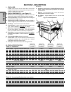
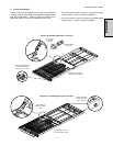
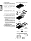
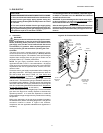
Figure 2-11 - Assembling and tensioning the conveyor
Tensioning
screws in slotted
holes (2 per side)
With tensioning
screws loosened,
frame sections can
be moved to adjust
belt tension
1-2" (25-50mm)
vertical deflection
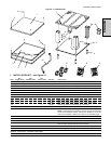
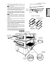
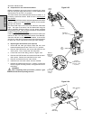
Figure 2-12 - Conveyor and master link orientation
Direction
of travel
CORRECT
master link
position
Incorrect
master link
position
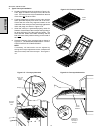
Pins on frame
fit into slots
on bracket
Folded
frame
1. Type 1 Conveyor Installation
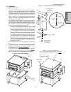
a. Unfold the conveyor frame so that it lies flat on the floor.
As you unfold the frame, check that the locator pins
shown in Figure 2-11 lock into the slots on the bracket.
b. Refer to Figure 2-11. Note the locations of the four
tensioning screws (2 per side) in the slotted holes on
the brackets. Loosen these screws to allow the
conveyor to be properly tensioned.
c. Lift the conveyor belt away from the frame, as shown
in Figure 2-11, to check the belt tension. The belt
should lift between 25-50mm.
If it is necessary to adjust the belt tension, gently push
the two conveyor frame sections closer together, or
further apart, as required. Then, re-check the tension
of the conveyor belt. Repeat this step as necessary
until the proper belt tension is achieved.
d. When the belt tension is correctly adjusted, tighten the
two tensioning screws on each side of the conveyor
frame. This fastens the two frame sections together
at the correct belt tension.
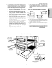
e. If it is necessary to add or remove conveyor links to
achieve the correct tension, OR if it is necessary to
reverse the conveyor belt for correct orientation, the
belt will need to be removed from the conveyor frame.
If this is necessary, perform the following procedure:
Remove the master links using long-nose pliers.
Then, roll up the belt along the length of the
conveyor frame.
Add or remove belt links as necessary to achieve
the correct belt tension.
Replace the belt on the conveyor frame. Check
that the conveyor belt links are oriented as shown
in Figure 2-12, and that the smooth side of the
conveyor belt faces UP.
f. Connect the inside master links. Check that the links
are oriented as shown in Figure 2-12.
g. Connect the outside master links. Note that the
outside master links each have an open hook on one
side. This hook aligns with the hooks along the sides
of the other conveyor links. See Figure 2-12.