


18
ENGLISH
B. Preparation for Use with Various Gases
Before proceeding to set up the oven for a specific gas, check
that the main gas supply valve and the circuit breaker/fused
disconnect are in the OFF ("O") position.
The main orifices must match the sizes shown in Table 1-5. If
necessary, replace the orifices. Refer to Part C,
Replacing the
Gas Orifices.
The orifice (manifold) pressure should be adjusted to the value
shown in Table 1-5 (in the
Description section) for the specific
gas type and location.
The actual heat input to the oven must match the rated heat
input. The input to the burner can be determined using the
orifice (manifold) pressure data or by the volume supplied
using the gas meter. Both of these procedures are described
in Part E,
Checking the Heat Input.
If the measured input does not correspond with the rated input
(shown in Table 1-5 in the
Description section of this Manual),
check first that the correct orifices are installed. If the orifices
are correct, check and correct the supply and orifice pressures
to obtain the correct input based on the gas meter reading.
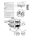
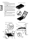
C. Replacing the Gas Orifices (if so required)
1. Check that the main gas supply valve and the circuit
breaker/fused disconnect are in the OFF ("O") position.
2. Remove AND RETAIN the hex screws that hold the rear
wall in place. Then, remove the rear wall panel.
3. Loosen the burner tube fitting, shown in Figure 2-24.
4. Remove AND RETAIN the two screws that hold the mani-
fold in place. Remove the manifold from the oven.
5. Remove and discard the two main orifices.
6. Install the two new main orifices into the manifold.
7. Replace the manifold into the oven. Fasten it in place with
the two original mounting screws, and tighten the burner
tube fitting.
WARNING
After completing these procedures, perform a gas
leak test before operating the oven.
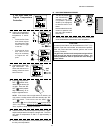
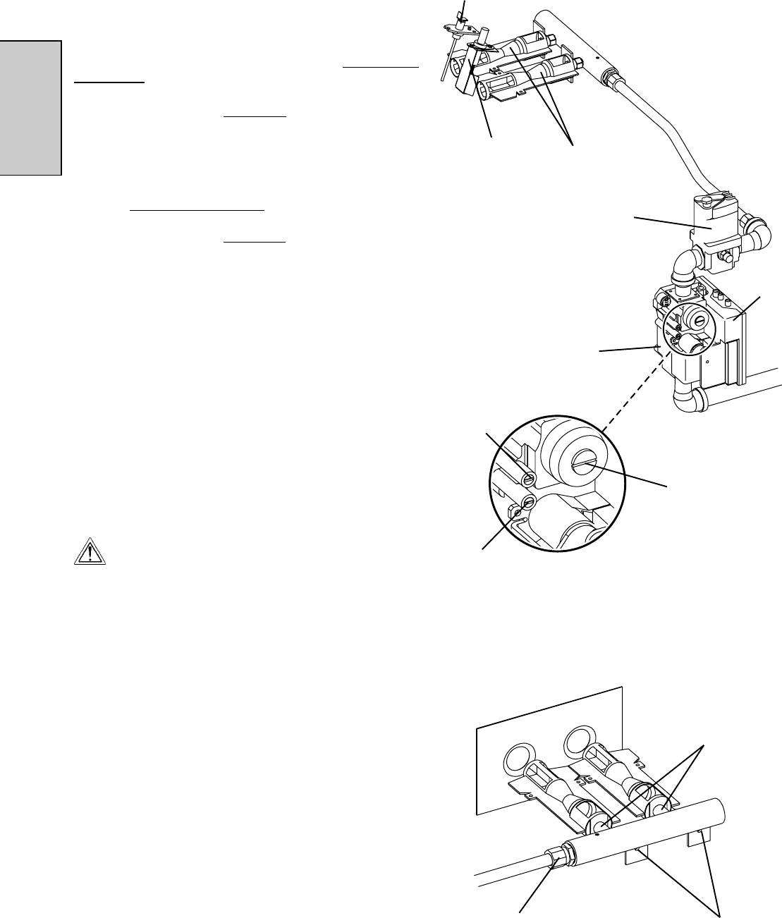
Figure 2-24
Burner
tube fitting
Screws (2)
Main orifices
(2)
In-shot
burners (2)
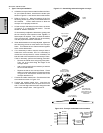
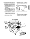
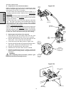
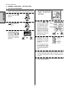
Figure 2-23
Ignitor
Flame
sensor
Modulating
gas valve
Gas
control
valve
Ignition
module
Manifold
pressure tap
(under cap
screw)
Inlet
pressure tap
(under cap
screw)
Pressure
adjustment screw
(governor - under
cap screw)
SECTION 2 - INSTALLATION