


15
ENGLISH
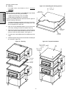
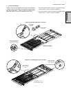
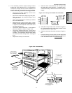
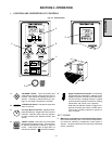
Figure 2-20 - Final assembly
Place chain cover
down over
conveyor sprocket
Slide crumb trays
into place from
front of oven
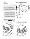
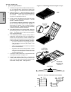
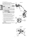
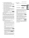
Figure 2-19 - Conveyor and master link orientation
Direction
of travel
CORRECT
master link
position
Incorrect
master link
position
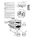
e. If it is necessary to add or remove conveyor links to
achieve the correct tension, OR if it is necessary to
reverse the conveyor belt for correct orientation, the
belt will need to be removed from the conveyor frame.
If this is necessary, perform the following procedure:
Remove the conveyor assembly from the oven
and place it flat on the floor.
Remove the master links using long-nose pliers.
Then, roll up the belt along the length of the
conveyor frame.
Add or remove belt links as necessary to achieve
the correct belt tension.
Replace the belt on the conveyor frame. Check
that the conveyor belt links are oriented as shown
in Figure 2-19, and that the smooth side of the
conveyor belt faces UP.
Connect the inside master links. Check that the
links are oriented as shown in Figure 2-19.
Connect the outside master links. Note that the
outside master links each have an open hook on
one side. This hook aligns with the hooks along
the sides of the other conveyor links. See Figure
2-19.
Replace the conveyor into the oven.
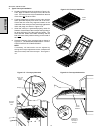
f. Install the drive chain between the conveyor drive
sprocket and the motor sprocket. To install the chain,
it will be necessary to lift the drive end of the conveyor
slightly.
Crumb trays rest in
support rails underneath
conveyor
SECTION 2 - INSTALLATION
g. Install the conveyor chain cover as shown in Figure 2-
20. Check that the chain cover does not bind on the
conveyor sprocket or drive shaft.
h. Slide the crumb trays into place as shown in Figure 2-
20.
i. Press the conveyor exit tray down over the edge of the
conveyor frame at the exit end of the oven. See Figure
2-20. Proceed to Section V,
Electrical Supply.
Press conveyor
exit tray down over
end of conveyor