


28
ENGLISH
II. MAINTENANCE - MONTHLY
A. Check that the oven is cool and the power is disconnected,
as described in the warning at the beginning of this Section.
B. Refer to Part C,
Conveyor Installation, in the Installation
section of this Manual. Then, remove the following compo-
nents from the oven:
Conveyor exit tray
Crumb trays
Chain cover
End plugs
Conveyor assembly
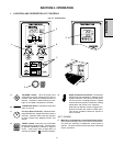
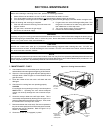
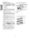
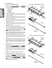
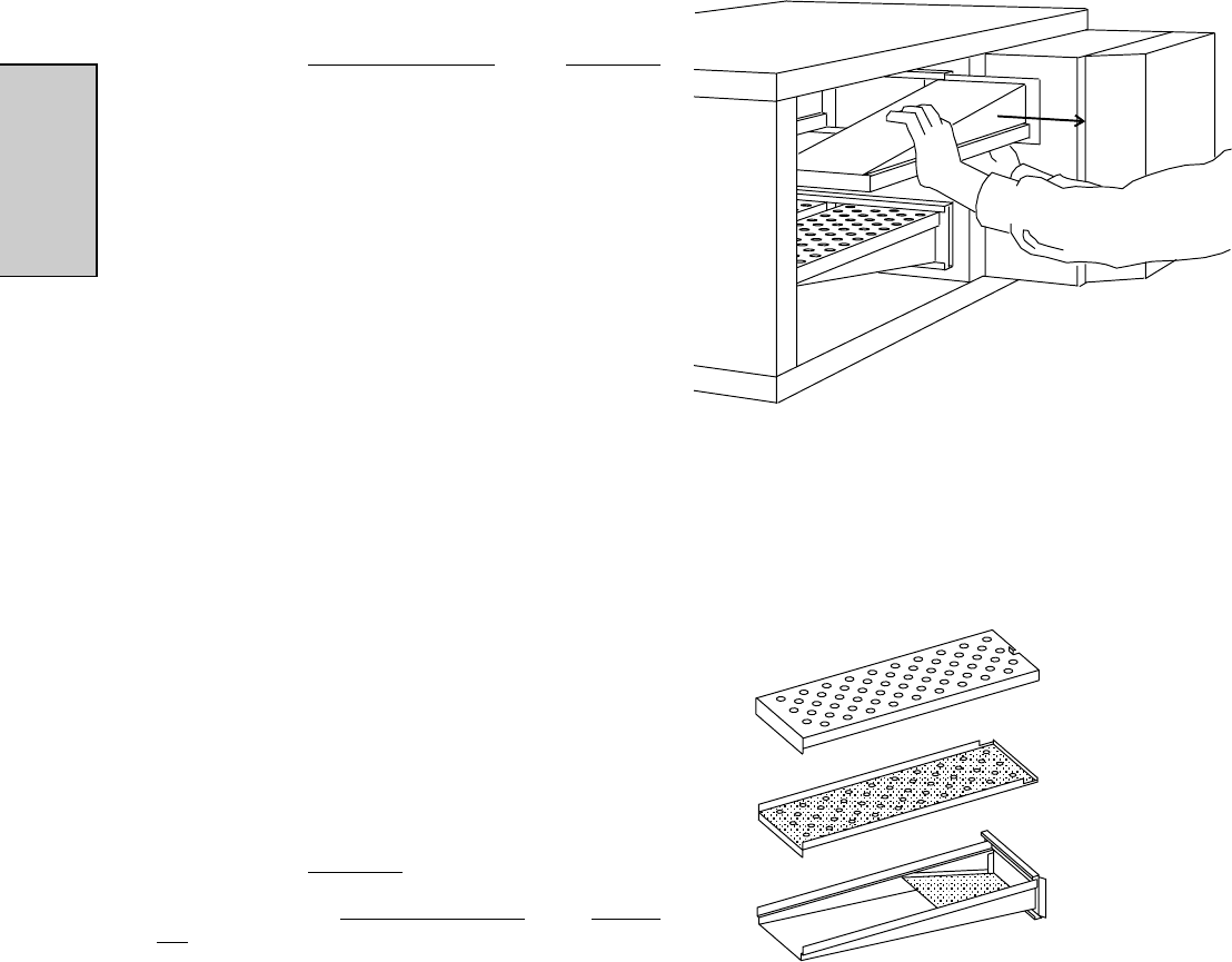
C. Slide the air fingers and blank plates out of the oven, as
shown in Figure 4-2. AS EACH FINGER OR PLATE IS
REMOVED, WRITE A "LOCATION CODE" ON IT WITH A
MARKER to make sure that it can be reinstalled correctly.
Example of markings:
(Top Row) T1 T2 T3 T4
(Bottom Row) B1 B2 B3 B4
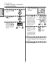
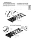
D. Disassemble the air fingers. See Figure 4-3. AS EACH
FINGER IS DISASSEMBLED, WRITE THE "LOCATION
CODE" FOR THE FINGER ON ALL THREE OF ITS PIECES.
This will help you in correctly reassembling the air fingers.
CAUTION
Incorrect reassembly of the air fingers will change the
baking properties of the oven.
E. Clean the air finger components and the interior of the
baking chamber using a vacuum cleaner and a damp cloth.
Refer to the boxed warnings at the beginning of this Section
for cleaning precautions.
F. Reassemble the air fingers. Then, replace them in the
oven, using the "location code" as a guide.
G. Install the end plugs on the oven. Then, reinstall the
conveyor.
H. Reattach the drive chain. Replace the chain cover.
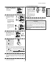
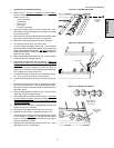
I. Check the tension of the conveyor belt as shown in Figure
2-7 (in Section 2,
Installation). The belt should lift between
25-50mm. If necessary, adjust the belt tension using the
procedure in Part C (
Conveyor Installation) in the Installa-
tion section of this Manual.
J. Replace the crumb trays and exit tray onto the oven.
Figure 4-2 - Removing Air Fingers and Plates
Figure 4-3 - Disassembling the Air Fingers
Outer Plate
SECTION 4 - MAINTENANCE
Inner plate
Manifold
III. MAINTENANCE - EVERY 3 MONTHS
A. Check that the oven is cool and the power is disconnected,
as described in the warning at the beginning of this Section.
B. Open the machinery compartment access panel. Vacuum
the inside of the compartment using a shop vacuum.
C. Tighten all electrical control terminal screws.