


30
ENGLISH
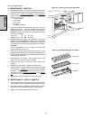
1. Type 1 Conveyor Split Belt Cleaning
a. Refer to Part C,
Conveyor Installation, in the Installation
section of this Manual. Then, remove the following compo-
nents from the oven:
Conveyor exit tray
Crumb trays
Chain cover
End plugs
Conveyor assembly
b. Remove the master links from each conveyor belt. Then,
roll the belts up along the length of the conveyor to remove
them from the frame.
c. Loosen (DO NOT REMOVE) the set screw on the outer drive
sprocket. Then, slide the drive sprocket off the end of the
drive shaft. See Figure 4-6.
d. Loosen (DO NOT REMOVE) the set screws on all four steel
spacers (2 per shaft), AND on all twelve conveyor belt
sprockets (6 per shaft).
e. Gently work the shaft sections out of the conveyor frame,
removing the conveyor belt sprockets as necessary. See
Figures 4-6 and 4-7.
f. Slide the two sections of each shaft apart.
g. Clean all of the shaft components thoroughly using a rag.
Then, lubricate each solid inner shaft, AND the interiors of
each hollow shaft, using a light food-grade lubricant.
DO
NOT lubricate the shafts using WD40 or a similar product.
This can cause the shafts to wear rapidly.
h. Slide the hollow shaft sections over the solid inner shafts.
Check that the hollow section that has a drive sprocket
attached is placed at the end of the the drive shaft.
i. Slide the reassembled shafts into the conveyor frame. As
the shafts are replaced, slide the steel spacers and con-
veyor belt sprockets onto the shafts. Refer to Figures 4-6
and 4-7.
j. After the shafts are properly aligned, position the steel
spacers against the ends of the bushings on the conveyor
frame. Tighten the set screws on the spacers to hold them
in place. Leave the conveyor belt sprockets loose at this
time.
k. Replace the outer drive sprocket. Tighten its set screw to
hold it in place.
l. Refer to Part C,
Conveyor Installation, in the Installation
section of this Manual to replace the conveyor belt. As you
replace the belt, position the conveyor belt sprockets.
m. After the belt is in place and the sprockets are correctly
positioned, tighten the set screws to hold the sprockets in
place.
n. Reinstall the end plugs and conveyor onto the oven.
o. Reattach the drive chains. Replace the chain cover.
p. Check the tension of the conveyor belt as shown in Figure
2-11 (in Section 2,
Installation). The belt should lift between
25-50mm. If necessary, adjust the belt tension using the
procedure in Part C (
Conveyor Installation) in the Installa-
tion section of this Manual.
q. Replace the crumb trays and exit tray onto the oven. Then,
skip ahead to Part E, "Blower Belt."
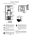
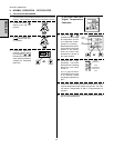
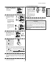
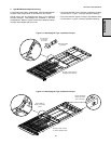
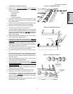
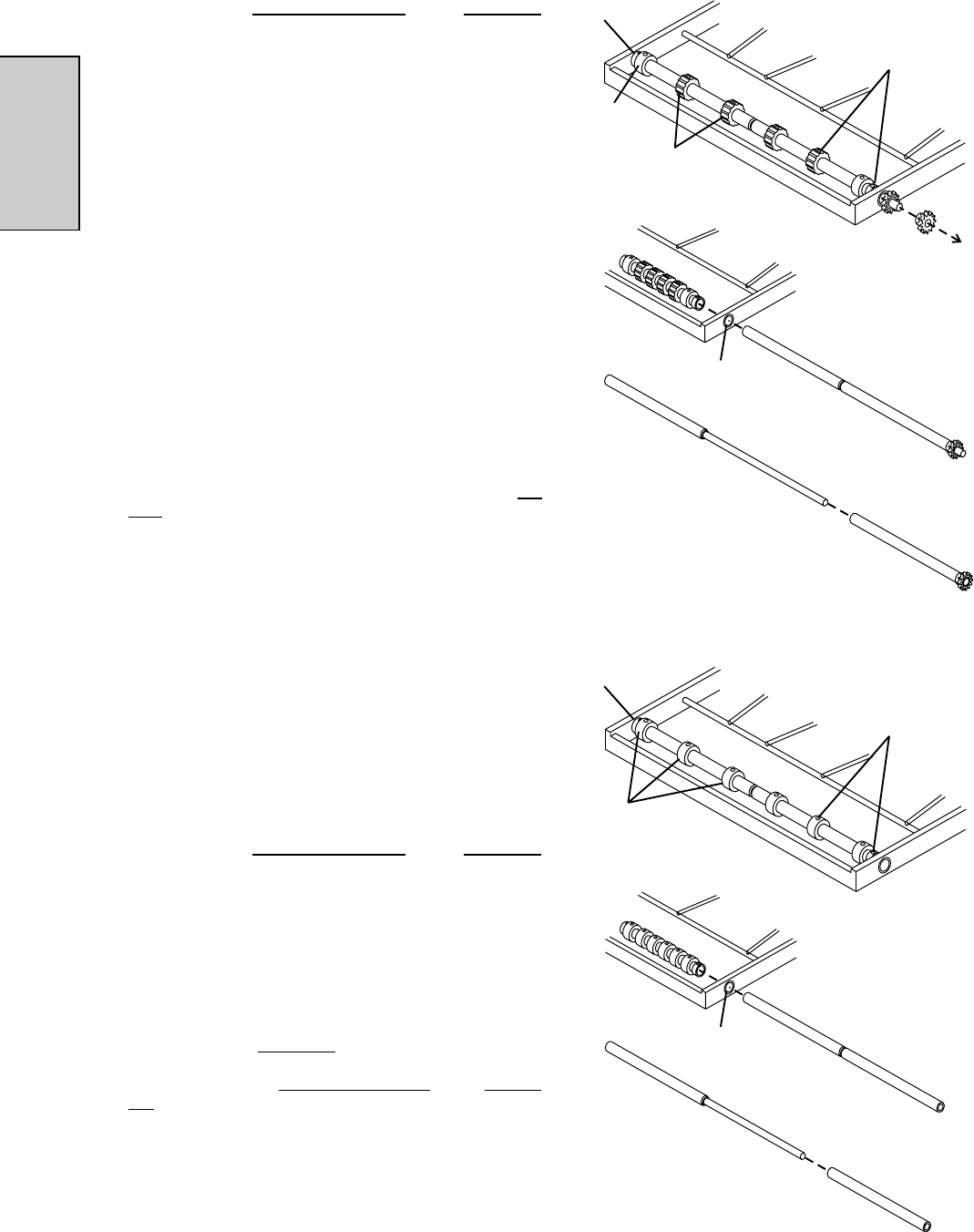
Figure 4-7 - Disassembling the idler shaft
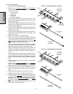
1. Remove outer
drive sprocket
Figure 4-6 - Disassembling the drive shaft
2. Loosen set
screws on belt
sprockets and
spacers (8)
3. Slide shafts out
of frame
Bushing
4. Disassemble,
clean, and
lubricate shafts
Smooth
sprocket (2)
Sprockets
w/teeth (4)
Spacer (2)
1. Loosen set
screws on belt
sprockets and
spacers (8)
2. Slide shafts out
of frame
Bushing
3. Disassemble,
clean, and
lubricate shafts
Smooth
sprockets (6)
Spacer (2)
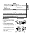
SECTION 4 - MAINTENANCE