


5
Installation precautions
Do not install this unit by suspending it, and do not install
it on its side.
While factoring in the weights of the unit and the load that
the unit will bear, select an installation location which is
conducive to fastening the unit securely and which is level
and without unevenness. Fasten the unit securely so that
it will not shake or be rickety when it is at rest or being
rotated. Failure to secure the unit properly or looseness
of the bolts may cause the product to fall off or fall down,
possibly resulting in an accident.
Bolts for installing the unit are not provided with the unit.
Select bolts which are sufficiently strong and made of a
material capable of with standing outdoor use.
The maximum load which the unit can bear is 22 lbs (10
kg) (excluding the housing).
The unit cannot be used with a load in excess of 22 lbs
(10 kg).
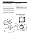
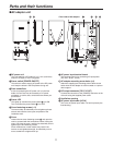
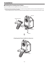
Upon completion of the pan/tilt head’s installation, mount
the housing. To prevent looseness in the places where
the unit is mounted, be absolutely sure to use parts such
as flat washers and spring washers for its installation.
The power must be off while the installation or connection
work is underway.
Do not set the power switch of the AC adapter to ON until
after checking that no mistakes have been made upon
completion of all the installation and connection work.
A ventilating fan is provided inside the housing. The fan
can be controlled using the H/F button on the controller
but it should normally be left at ON. Furthermore, d
o
not block it or obstruct the ventilation while the unit is
operating. Otherwise, heat will build up inside, possibly
causing a fire. The ventilating fan is a consumable: as
a general rule, replace it after abo
ut 40,000 hours of
operation.
(Be absolutely sure to ask your dealer to replace the fan.)
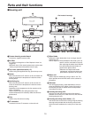
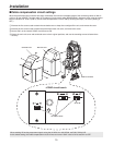
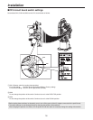
Steps to be taken prior to installation
The AW-PH650 has function selector switches on its
main unit (pan/tilt head) and housing.
Since it may prove difficult to change the positions
of these switches after installation, refer to
cable
compensation circuit settings (page 15), CPU circuit
board switch settings (page 16) and
settings of
the camera control selector switch inside the housing
(page 25) prior to installation.
Then set the switches to the positions that correspond to
the operating conditions.
Be absolutely sure to use water-proof connecting cables.
Do not install the unit where the temperature will drop
below
–4°F (–20°C) or rise above 113°F (45°C) since
operation will become unstable under these temperature
conditions.
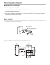
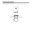
Be absolutely sure to use the AC adapter provided
with the unit as the power source of the pan/tilt head.
(Batteries or other power supplies cannot be used.)
The cable for connecting the power supply to the
AC adapter is locally
purchased. Read the operating
instructions, and heed all the safety precautions to
connect the cable.
Do not turn the rotating part of the pan/tilt head by hand.
If it is dropped or subjected to strong impact, it may fail or
malfunction.
Install the unit and set a travel range (limiters) to ensure
that it will not come into contact with any objects in the
vicinity when the unit including the housing has swiveled.
Do not operate the controls on the pan/tilt head under
any circumstances while installation or other work is
underway.
Before checking the pan/tilt head’s operation and before
actually using it, check that nobody is within the range of
its rotation.
Do not install the unit in a kitchen or other location where
there is a lot of oil or grease.
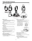
Check the following accessories supplied.
Product QTY Specification
1 Power cable 1 Approx. 98.4 ft. (30 m)
2 Multi cable 1 Approx. 32.8 ft. (10 m)
3 Camera cable 1 For convertible camera
4 Camera cable 1 For AK-HC900 series
5 Camera cable 1 For AK-HC1500
6 Lens holder 1 For a large lens
7 Screws for lens holder 2 For M5 and M6
8 Washers for lens holder 2 ø6
9 String 1 Approx. 2.8 ft. (85 cm)
10 Camera mounting spacer 1
11
Screws for camera mounting spacer
4 1/4", length: 13 mm
12
Washers for camera mounting spacer
4 ø6
13 Positioning screw 1 M5, length: 8 mm
14 Pole mounting plate (AC adapter) 1
15 Screws for pole mounting plate 4 M8, length: 14 mm
16 Washers for pole mounting plate 8 ø8
17 Allen keys 3 For M5, M6 and M8
18 Housing mount frame 1
19 Screws for housing mount frame 4 M5, length: 30 mm
20 Washers for housing mount frame 8 ø5
21 Filter 1
22 Cable ties 5 Approx. 100 mm