


9
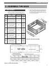
ASSEMBLE THE BASE
A. BASE ASSEMBLY
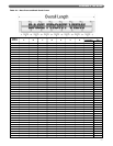
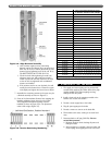
1. Collect the crates containing the Base Assembly parts.
Table 2.1 (on page 11) shows the quantity of each
crate required. The crates contain the following parts:
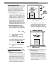
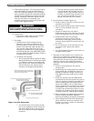
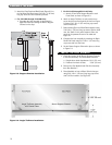
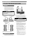
2. Open crate number 2. Remove the End Panels and
mount a Support Channel Clip toward the rear on
each panel as shown in Figure 2.2 using 1/4"-20 x
1/2" (13 mm) long round head machine screws and
1/4" lock washers provided.
2. ASSEMBLE THE BASE
2
2AA
2BB
2CC
2DD
2EE
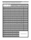
Crate
Right End Panel Sub-Assembly
Left End Panel Sub-Assembly
Burner Support Channel Clips (2)
Front Panel Sub-Assembly
Back Panel Sub-Assembly
Burner Support Channel
Front Panel Support Bracket
Section Assembly Kit
Front Panel Sub-Assembly
Back Panel Sub-Assembly
Burner Support Channel
Angle Tie Brace
Front Panel Support Bracket
Section Assembly Kit
Front Panel Sub-Assembly
Back Panel Sub-Assembly
Burner Support Channel
Angle Tie Brace
Front Panel Support Bracket
Section Assembly Kit
Front Panel Sub-Assembly
Back Panel Sub-Assembly
Burner Support Channel
Angle Tie Brace
Front Panel Support Bracket
Section Assembly Kit
Front Panel Sub-Assembly
Back Panel Sub-Assembly
Burner Support Channel
Angle Tie Brace
Front Panel Support Bracket
Section Assembly Kit
Items
90338
90340
90341
90342
90343
90344
Sub-Assembly #
GG-2105
GG-2106
GG-2070
GG-2080
GG-2081
GG-2066
GG-2069
GG-1030
GG-2080-1
GG-2081-1
GG-2066-1
GG-2065
GG-2069
GG-1030
GG-2080-2
GG-2081-2
GG-2066-2
GG-2065
GG-2069
GG-1030-1
GG-2080-3
GG-2081-3
GG-2066-3
GG-2065
GG-2069
GG-1030-2
GG-2080-4
GG-2081-4
GG-2066-4
GG-2065
GG-2069
GG-1030-3
Part #
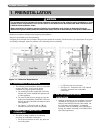
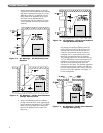
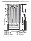
Figure 2.2: Steel Base Assembly
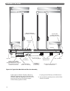
Figure 2.1: Boiler Base Assembly