


21
PIPE THE BOILER
2. On pumped return systems, install a boiler cock after
the pump to allow throttling of the pump discharge.
The pressure after the boiler cock should be no more
than 5 psig (35 kPa) above the boiler operating
pressure. Pumping the water into the boiler too fast
will cause collapse of the water level and level
control problems.
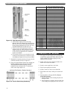
3. Size the equalizer per Table 5.1.
4. Pipe the Hartford loop tee so the inside top of the
close nipple is 2 to 4 inches (51 to 102 mm) below
the boiler water line.
5. If the pump discharge is looped overhead, above the
boiler water line, install spring-loaded check valves at
both the pump discharge and the connection to the
boiler return.
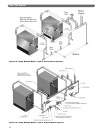
D. MULTIPLE BOILER INSTALLATIONS
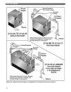
1. Figure 5.5 shows typical piping for multiple boiler
Gravity Return systems. Figure 5.6 shows typical
piping for multiple boiler Pumped Return systems.
2. Provide separate feed lines for multiple boiler
pumped return systems. Use either separate feed
pumps or solenoid valves to isolate feeding of the
boilers. This is needed to provide reliable level
control and avoid nuisance performance problems.
3. Condensate return units are not effective for multiple
boiler installations since they do not respond to the
needs of the boilers. Always use Boiler feed units.
a. Install a Float and Thermostatic trap at the boiler
water level on each of the multiple boilers on a
pumped return system. This prevents flooding of
idle boilers due to condensation of steam.
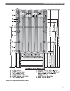
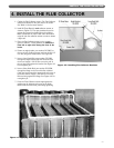
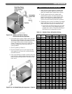
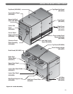
Figure 5.4: Left Hand Piping Arrangement – Typical
Figure 5.3: Supply and Return Piping –
Counterflow Gravity Systems
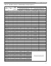
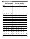
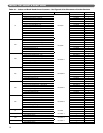
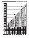
Boiler Header
End Risers Interm. Risers Equalizers
Model Size
No. Size No. Size No. Size
211A-04 4" 1 4" - - 1 2-1/2"
211A-05 5" 1 5" - - 1 2-1/2"
211A-06 5" 1 5" - - 1 2-1/2"
211A-07 5" 1 5" - - 1 2-1/2"
211A-08 6" 2 5" - - 1 2-1/2"
211A-09 6" 2 5" - - 1 2-1/2"
211A-10 6" 2 5" - - 1 3"
211A-11 6" 2 5" - - 1 3"
211A-12 8" 2 5" - - 1 3"
211A-13 8" 2 5" - - 1 3"
211A-14 8" 2 5" - - 1 3"
211A-15 8" 2 6" - - 1 3"
211A-16 8" 2 6" - - 2 4"
211A-17 8" 2 6" - - 2 4"
211A-18 8" 2 6" 1 3" 2 4"
211A-19 8" 2 6" 1 3" 2 4"
211A-20 8" 2 6" 1 3" 2 4"
211A-21 8" 2 6" 1 3" 2 4"
211A-22 8" 2 6" 2 3" 2 4"
211A-23 8" 2 6" 2 3" 2 4"
211A-24 10" 2 6" 2 3" 2 4"
211A-25 10" 2 6" 3 3" 2 4"
211A-26 10" 2 6" 3 3" 2 4"
211A-27 10" 2 6" 4 3" 2 4"
211A-28 10" 2 6" 4 3" 2 5"
211A-29 10" 2 6" 5 3" 2 5"
211A-30 10" 2 6" 5 3" 2 5"
211A-31 10" 2 6" 6 3" 2 5"
211A-32 10" 2 6" 6 3" 2 5"
211A-33 10" 2 6" 7 3" 2 5"
211A-34 10" 2 6" 7 3" 2 5"
211A-35 10" 2 6" 7 3" 2 5"
211A-36 10" 2 6" 8 3" 2 5"
211A-37 10" 2 6" 8 3" 2 5"
211A-38 10" 2 6" 8 3" 2 5"
211A-39 10" 2 6" 9 3" 2 5"
211A-40 10" 2 6" 9 3" 2 5"
211A-41 10" 2 6" 10 3" 2 5"
211A-42 10" 2 6" 10 3" 2 5"
211A-43 10" 2 6" 11 3" 2 5"
211A-44 12" 2 6" 11 3" 2 5"
211A-45 12" 2 6" 12 3" 2 5"
211A-46 12" 2 6" 12 3" 2 5"
Table 5.1: Header, Risers & Equalizer Sizing