


12
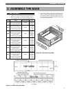
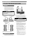
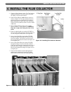
ASSEMBLE THE BASE
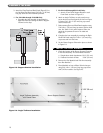
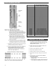
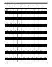
4. Place only the Burners with pilots mounted in the
locations given in Table 2.2. Install the Burners by
slipping the opening on the front of the burner over
the orifice adapter and slipping the pin on the end of
the burner into the hole in the Burner Support
Channel directly opposite the orifice.
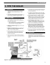
5. Cut and fit the 1/4" aluminum tubing provided from
the pilot gas shut-off device(s) to the pilot burners.
6. Do not install the remaining burners until the Boiler
Sections are installed.
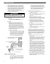
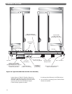
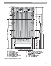
1/4" X 1-1/2"
(38 mm) long Nipple
(2) 1/4" Street Elbow
Imperial #69F Elbow
1/8" NPT x 1/4" O.D. Tubing
PB-H91BG-2 or
H-V8046C
Pilot Gas Valve
1/4" x 1/8"
Hex Bushing
3/8" Thermopilot
Valve(s) H17CA
(2) 5/16"-18 x 3/4" (19mm) long
Square Head Set Screw
3/8" x 1/4" Elbow
Imperial #68F
1/4" NPT x 3/8" O.D.
Tube Straight Connector
Ignition Control & Relay
Mounting Box Assembly
(Standard HSP System, X-3011-3)
(Other panels mounted on
jacket front, left side)
3/8" Pipe Cap
Pipe Cap
Test Plug
Mounting Clamp
GG-3052 thru GG-3052-3
Orifice Spud
X-4026
Manifold Weldment
GG-4084 thru GG-4084-46
3/8" x 3/8" x 1/4" Tee
Figure 2.5: Typical Gas Manifold and Pilot Line Assembly