


32
INSTALL CONTROLS AND TRIM
A. INSTALL SAFETY VALVE(S)
1. Pipe the pop safety valve(s) in the 3" tappings
located on the right or left end sections. Make sure
the relief valve sizing meets local code requirements.
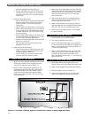
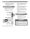
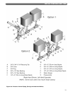
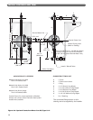
B. INSTALL BLOWDOWN VALVES
1. Install a 1-1/2" full port ball valve in each of the
tappings provided at the lower back of the end
sections. See Figure 8.1.
2. Pipe the valve discharge to a floor drain if available or
apply a nipple and cap to close off when not in use.
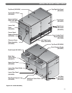
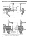
C. INSTALL LOW WATER CUT-OFF(S)
1. Mount the float type low water cut-off and gauge
glass in the tappings provided in the front of either
end section.
2. Do not apply piping which would raise or lower the
location of the cut-off relative to the tappings in the
boiler. Raising the water level over the design height
will cause water carryover to the system.
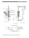
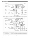
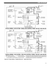
3. For correct location of typical low water cut-off/feeder
or low water cut-off/pump control, see Figures 8.3
through 8.6.
4. Mount the probe type low water cut-off supplied with
the boiler. The end sections have 3/4" tappings in the
front for mounting the probe low water cut-off
auxiliary control. See Figure 3.3.
a. The standard probe control is Hydrolevel Model
650P. This control is automatic reset type.
b. When a manual reset control is required, the boiler
can be supplied with Hydrolevel Model 550P.
5. Provide each float low water cut-off with a blowdown
valve. Pipe the blowdown away from traffic to a floor
drain if available. The blowdown valve is required for
proper maintenance of the control.
6. Maintain a height of 40-1/2" (1029 mm) from boiler
foundation to the normal water level.
7. When using multiple float type Controls: Always pipe
the controls off of the same tappings to the boiler.
Do not mount on different ends of the boiler or in
different tappings. This can cause erratic operation
and nuisance problems with the controls.
D. INSTALL PRESSURE CONTROLS
1. Pipe the Steam Pressure Gauge and Boiler Limit and
Operating Pressure Controls as shown in Figure 8.2.
Connect the control assembly to the 1/2" tapping on
the right end of the boiler.
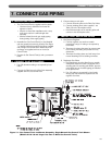
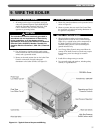
8. INSTALL CONTROLS AND TRIM
Pipe the discharge of the Safety Relief Valve(s) away
from any traffic area, preferably to a floor drain. This
is necessary to prevent injury should the valve
discharge.
Pipe the discharge full size of valve outlet.
CAUTION
Make sure that the gas ignition system components,
electrical controls, junction boxes and electrical
panels are protected from water (dripping, spraying,
rain, etc.) during boiler operation and service
(circulator or pump servicing, control replacements
or other).
CAUTION
Figure 8.1: Blowdown Valve Piping