


36
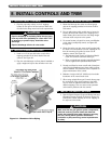
INSTALL CONTROLS AND TRIM
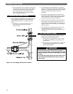
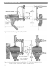
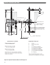
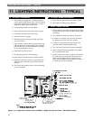
Figure 8.6: Optional Feeder/Low Water Cut-Off, Type 51-2
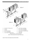
APPLICATION OF 51 FEEDERS
Models 211A-24 thru 211A-39
One 51-S-2 Feeder/Cutoff
Models 211A-40 and Larger
Two 51-2 Feeder/Cutoffs
Consult Factory for proper application of feeders.
Always use a pump control and boiler feed system
instead when possible.
Normal Water Line
Feeder Closing Level
(Mark on Casting)
2" (51 mm)
3/4"
19 mm)(
12-7/8"
327 mm)(
6-11/16"
170 mm()
25-1/8" (638 mm)
Boiler Foundation
10-3/8"
264 mm)(
10-7/8" (276 mm)
36" (914 mm )
4-1/8"
105 mm()
8-1/8"
206 mm)(
Install 1" Blowoff Valve
Burner Cut-Off Level is ( ) Below
Center Line on 51-2 and 51-S-2 Controls
[ ( ) Below Normal Water Line]
1-1/2" 38 mm
2-3/4" 70 mm
Control Center Line
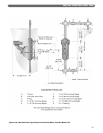
The connected fittings shown on this
drawing are to be supplied by the installer.
J
F
A
A
A
B
B
D
DD
C
CC
C
C
G
H
E
Models 211A-04 thru 211A-23
One 51-2 Feeder/Cutoff
SUGGESTED FITTINGS LIST
A
B
C
D
E
F
G
H
J
1" Cross
1" Ground Joint Union
1" Plug
1" x ( ) long Nipple
1" x ( ) long Nipple
1" x ( ) long Nipple
1" x ( ) long Nipple
1" x ( ) long Nipple
3" x 1" Bushing
3" 76 mm
5-1/2" 140 mm
8" 203 mm
8-1/4" 210 mm
19-1/2" 495 mm
40-1/2"
(1029 mm)