


16
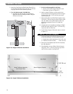
e. Draw sections together evenly, alternating
between top lug and bottom lug in increments of
20 ft.-lbs. (27 N
·
m). Continue until both top and
bottom lugs are tightened to 60 ft.-lbs. (81 N
·
m).
DO NOT EXCEED 60 FT.-LBS (81 N
·
m).
f. Check the level while tightening to make sure
alignment stays true. Also make sure sections
remain square with the Base from front to back
as the tie rods are tightened and as additional
sections are installed.
g. If the sections tend to run out of plumb, this will
usually be at the bottom front. Loosen the upper
nuts slightly and tighten the lower ones to adjust.
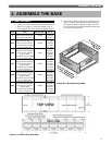
7. Assemble the remaining sections in the same way for
a finished assembly as shown in Figure 3.3.
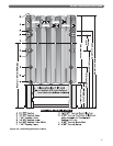
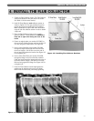
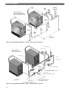
8. Some of the Intermediate Sections have tappings for
installing additional steam risers from the boiler.
These Tapped Intermediate Sections must be
installed as shown in Figure 3.5A. The placement
order is left to right (Figure 3.5).
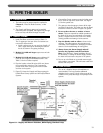
C. HYDROSTATIC TEST THE BOILER
1. The supply and return piping can be permanently
erected before applying the Boiler Jacket if the pipe
nipples applied to the boiler tappings are long
enough to clear the jacket.
2. Install a drain cock in the tapping provided at the
bottom rear of each end section.
3. Provide a water supply line to the boiler.
4. Plug all open tappings in the boiler.
5. Provide a means to vent air as the boiler fills.
6. Fill the boiler with water, venting air as water level
rises.
7. Pressurize boiler to 45 psig (310 kPa). Do not
exceed this pressure.
a. Maintain pressure while checking all joints and
fittings for leaks.
b. After inspection is complete, drain the boiler and
remove plugs from tappings that are to be used.
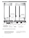
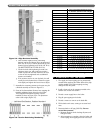
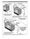
Figure 3.4: Align Sections Vertically
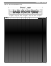
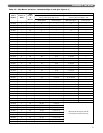
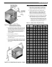
Figure 3.5: Section Positioning Numbering
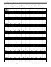
Boiler Model Number
Place Tapped Intermediate Sections
as Positions (numbered Left to Right)
211A-18 10
211A-19 10
211A-20 11
211A-21 11
211A-22 8, 16
211A-23 8, 16
211A-24 9, 17
211A-25 7, 13, 19
211A-26 7, 13, 20
211A-27 7, 12, 17, 22
211A-28 5, 11, 17, 23
211A-29 5, 10, 15, 20, 25
211A-30 6, 11, 16, 21, 26
211A-31 6, 10, 14, 18, 22, 26
211A-32 6, 11, 15, 19, 23, 27
211A-33 5, 9, 13, 17, 21, 25, 29
211A-34 5, 9, 13, 17, 22, 26, 30
211A-35 5, 9, 13, 18, 23, 27, 31
211A-36 5, 9, 13, 17, 21, 25, 29, 33
211A-37 5, 9, 13, 17, 21, 25, 29, 33
211A-38 4, 8, 12, 17, 22, 27, 31, 35
211A-39 4, 8, 12, 16, 20, 24, 28, 32, 36
211A-40 4, 8, 12, 16, 21, 25, 29, 33, 37
211A-41 4, 8, 12, 16, 19, 23, 26, 30, 34, 38
211A-42 4, 8, 12, 16, 20, 23, 27, 31, 35, 39
211A-43 4, 7, 11, 14, 18, 22, 26, 30, 33, 37, 40
211A-44 4, 8, 12, 16, 19, 23, 26, 29, 33, 37, 41
211A-45 4, 7, 11, 14, 18, 21, 25, 28, 32, 35, 39, 42
211A-46 4, 7, 11, 14, 18, 22, 25, 29, 33, 36, 40, 43
Figure 3.5A: Section Position Numbering
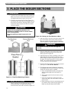
PLACE THE BOILER SECTIONS