


10
ASSEMBLE THE BASE
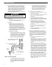
3. Attach the Front Panel and Back Panel (Figure 2.2) to
the Left Hand End Panel using 5/16"-18 x 1" (25 mm)
long cap screws and hex head nuts provided.
4. For 211A-04 through 211A-08 Only:
a. Complete the base assembly by attaching the
Right End Panel and setting the Burner Support
Channel on the clips.
5. For 211A-09 through 211A-46 Only:
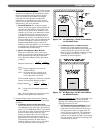
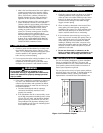
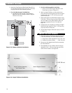
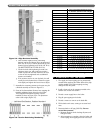
a. Attach a Front Panel Support Bracket to each
Front Panel as shown in Figure 2.3.
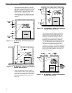
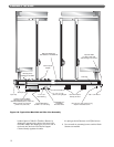
6. Attach an Angle Tie Brace at each panel joint to
secure the front and back panels as shown in Figure
2.4 using 5/16"-18 x 1" (25 mm) long cap screws
and hex head nuts.
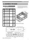
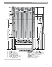
7. Bolt remaining Front and Back Panels together using
5/16"-18 x 1" (25 mm) long cap screws and hex head
nuts. See Table 2.1 for panels required. Place the
panels in the positions shown in the table and
Figure 2.1.
8. Complete the base assembly by attaching the Right
Hand End Panel using 5/16"-18 x 1" (25 mm) long
cap screws and hex head nuts.
9. Set the Burner Support Channels in place as shown
in Figure 2.1.
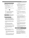
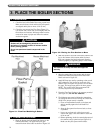
B. INSTALL THE PILOT BURNERS
1. Check the location of the Burner Support Channels
in the Base Assembly. The dimensions should be:
a. Height above boiler foundation: 6-3/4" (171 mm)
b. Distance from back of Base: 3-3/4" (95 mm)
2. Remove the Gas Manifold and Pilot Line Assembly
from Box Number 7.
3. Place Manifold on front of Base. Bolt the hangers
using 5/16"-18 x 1" (25 mm) long long cap screws
with 5/16" flat washers. See Figure 2.5.
Figure 2.3: Support Bracket Installation
Figure 2.4: Angle Tie Brace Installation