


37
WIRE THE BOILER
A. CONNECT SUPPLY WIRING
1. All wiring must be done in accordance with local
codes, the National Electrical Code ANSI/NFPA70
and/or the Canadian Electrical Code Part I, CSA
C22.1, Electrical Code and other controlling
agencies or governing bodies.
2. Use #14 gauge or heavier wire for supply wiring.
Protect the circuit with a fused disconnect switch (by
others) and a grounded neutral.
3. Mount an electrical junction box on the boiler Front
Panel for connection of supply wiring and
distribution to the boiler controls. See Figure 9.1.
B. PREPARE REMAINING CONTROLS
1. Mount the control transformer on the junction box as
shown in Figure 9.1.
2. Mount a junction box near each Gas Control Train
for connection of conduit and wiring distribution to
the gas train components.
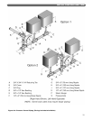
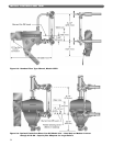
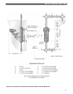
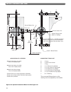
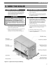
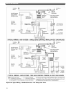
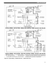
C. INSTALL CONTROL WIRING
1. Wire the boiler according to the wiring diagram
supplied with the boiler (in the Control Envelope).
Figure 9.1 is a typical layout of the components on
the boiler. Figures 9.2 and 9.3 are examples of
standard wiring systems. Use these drawings for
general reference only.
2. Low Energy Safety Control wiring must follow the
contour of the boiler. Some local codes may require
that all wiring, even low voltage, be routed in
conduit.
3. Install all line voltage wiring in conduit.
4. Do not install single pole switches, including safety
controls, in a grounded line.
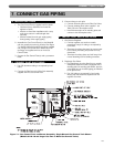
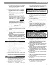
9. WIRE THE BOILER
The boiler/burner must be electrically grounded in
accordance with the requirements of the authority
having jurisdiction, or in the absence of such
requirements, with the current edition of the National
Electrical Code, ANSI/NFPA Number 70 and/or the
Canadian Electrical Code Part I, CSA C22.1, Electrical
Code.
NOTICE
Figure 9.1: Typical Control Layout and Wiring