


24
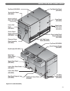
INSTALL THE JACKET & DRAFT HOOD
• Continue applying Front Panels this way.
• Slip the right edge of the last Front Panel under
the Right Front Corner Panel. Line up the holes
and secure with #10 x 1/2" (13 mm) long sheet
metal screws.
5. Install the Jacket Rear Panels:
• Slip the offset flange of the first Upper Rear Panel
under the edge of the Left Rear Corner Panel.
Secure with #10 x 1/2" (13 mm) long sheet
metal screws.
• Attach the first Lower Rear Panel in the same way.
• Attach a Rear Panel Support Leg on the inside of
the Upper Rear Panel. The flanges point toward
the boiler. Attach with #10 x 1/2" (13 mm) long
sheet metal screws.
• Install a Panel Support Angle on the inside top of
the Upper Rear Panel (See Figure 6.2). Use #10
x 1/2" (13 mm) long sheet metal screws.
• Install the remaining Upper Rear and Lower Rear
Panels in the same way.
• Place the edge of the last rear panel over the
Right Rear Corner Panel.
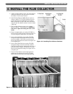
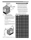
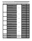
6. Install the Draft Hood Sections:
• Start from the left of the boiler (facing the front).
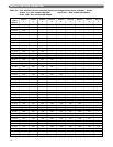
Apply the Draft Hood sections from left to right
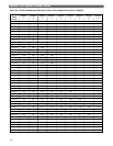
in the order given in Table 6.2.
• Use two #10 x 1/2" (13 mm) long sheet metal
screws for each Flue Collector section.
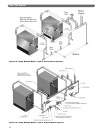
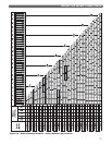
F. APPLY JACKET TOP PANELS
1. Apply the jacket top panels working from left to right
(facing front of boiler). Place the panels from the
cartons in the sequence given in Figure 6.3.
2. Mount a Panel Support Angle (GG-6027) on the
back bottom edge of each Top Panel with the long
flange pointed down. Peel the insulation slightly
away from the back edge of the panel for better
contact. Secure with one #10 x 1/2" (13 mm) long
sheet metal screw.
3. Slide the left hand offset flange of the first Top Panel
under the Top Left End Panel. Place the front flange
of the Top Panel over the Front Panel. Line up the
holes and secure with #10 x 1/2" (13 mm) long
sheet metal screws.
4. Slide the left hand edge of each additional panel
under the panel to its left. Secure with #10 x 1/2"
(13 mm) long sheet metal screws.
5. Apply the last Top Panel in the same way. Place its
right hand edge over the Top Right End Panel. Secure
with #10 x 1/2" (13 mm) long sheet metal screws.
6. Check for loose or missing screws as you complete
the jacket assembly.
G. APPLY LOWER END PANELS
1. THIS APPLIES TO ALL BOILER SIZES.
2. The parts are packed in carton #12.
3. Attach an End Panel Cover Plate to the opening in
the Lower End Panel (GG-6022) if the tapping in the
boiler is not being used. Secure with two #10 x 1/2"
(13 mm) long metal screws.
4. Apply a Lower End Panel to each end of the boiler,
securing to the Corner Panels with eight #10 x ½”
(13 mm) long sheet metal screws. Attach to the
Upper End Panels with two #10 x ½” (13 mm) long
sheet metal screws.
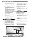
H. APPLY PLATES AND LABELS
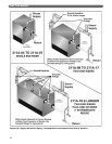
1. Mount Boiler Rating Label, Agency Plates and
Caution Labels in the Upper Right End Jacket Panel.
2.
Plates to be field applied are packed in Box Number 7.
3. Place these plates as shown in Figure 6.1.
4. Secure metal plates with #6 x 6 mm (1/4") sheet
metal screws. Apply all adhesive-backed labels.
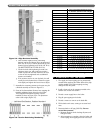
FIGURE 28
Figure 6.1: Location of Rating, Agency and Instruction Plates on Upper Right End Panel